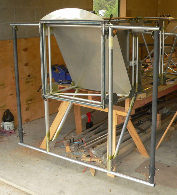
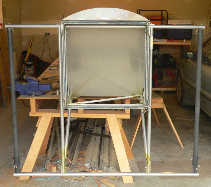
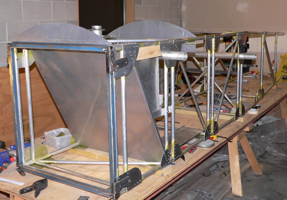
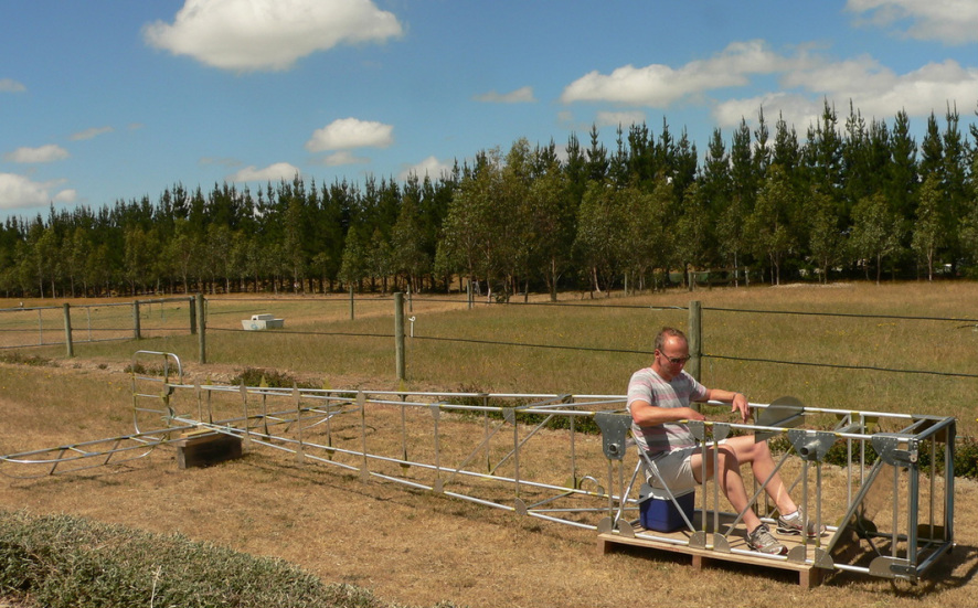
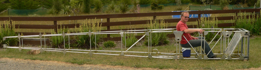
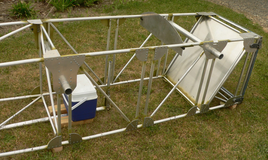
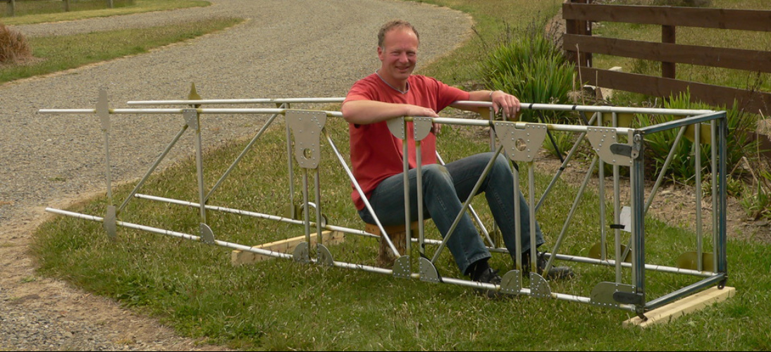
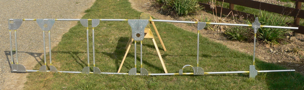
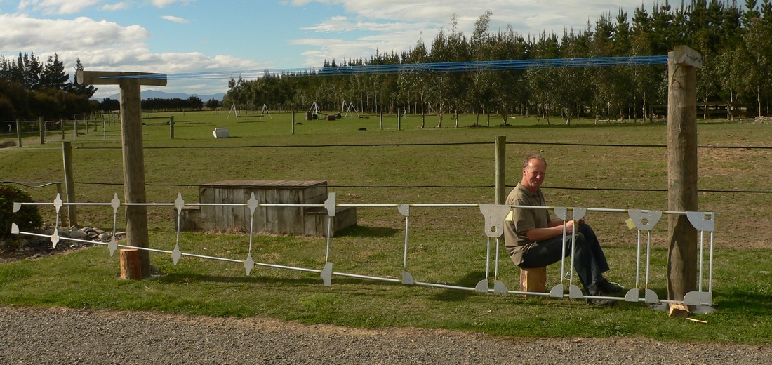
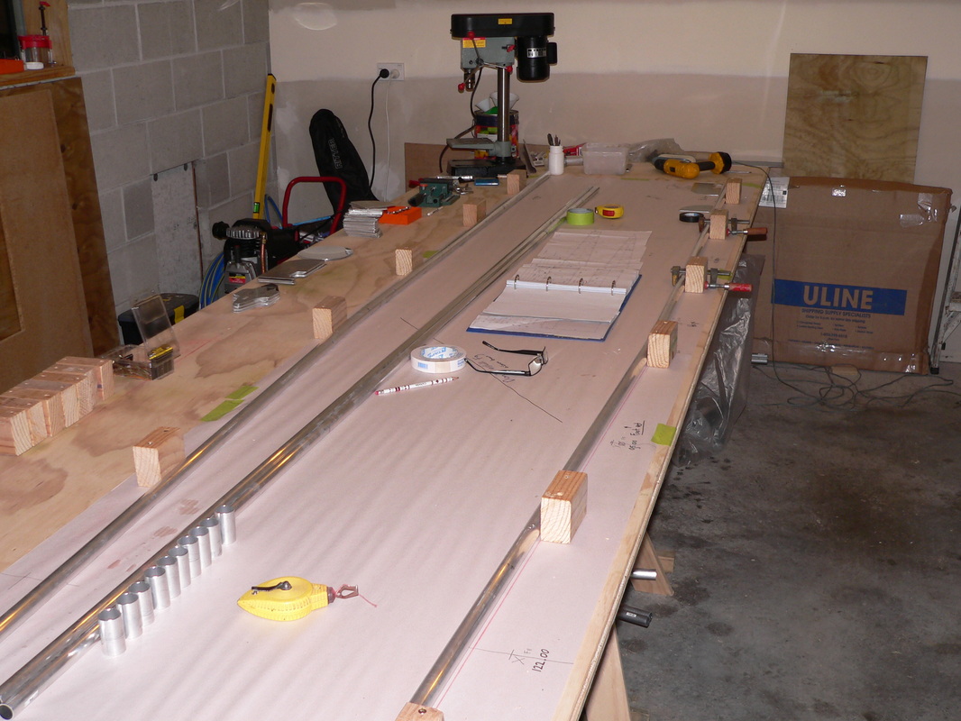
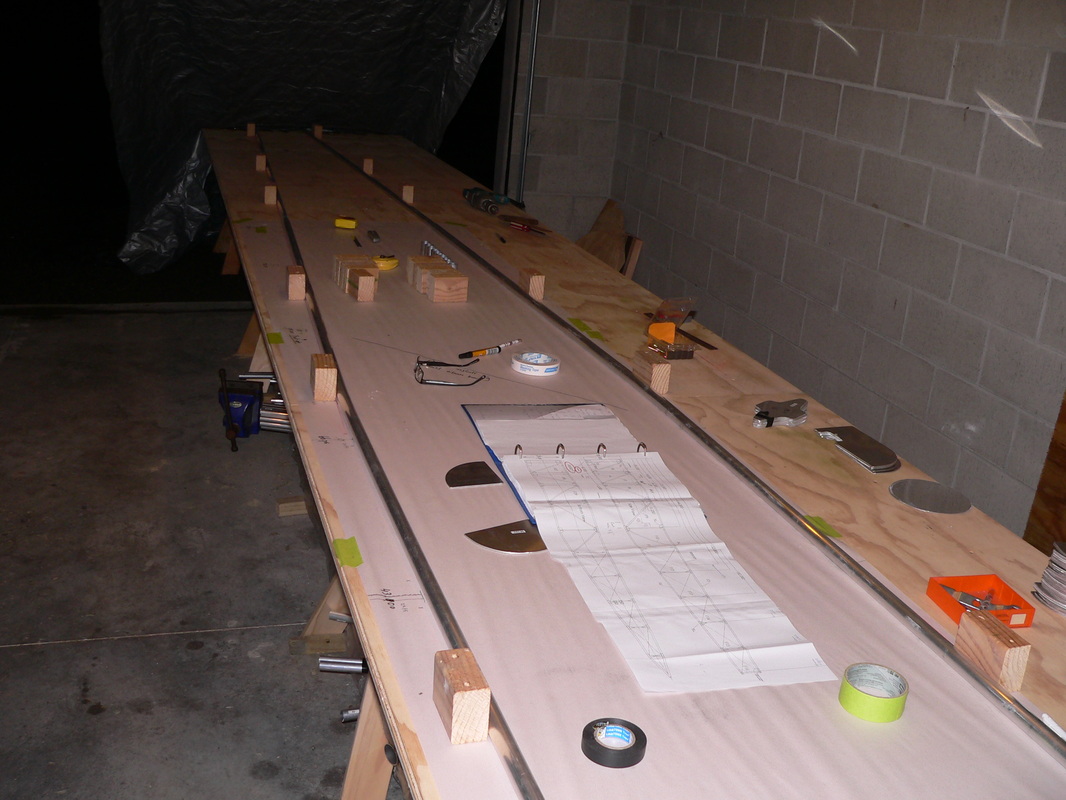
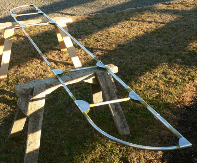
Finished all of the landing gear. Getting the front of the fuselage ready for the move into the shed.
Going to do some more work on the fuselage now, before finalizing the landing gear..........
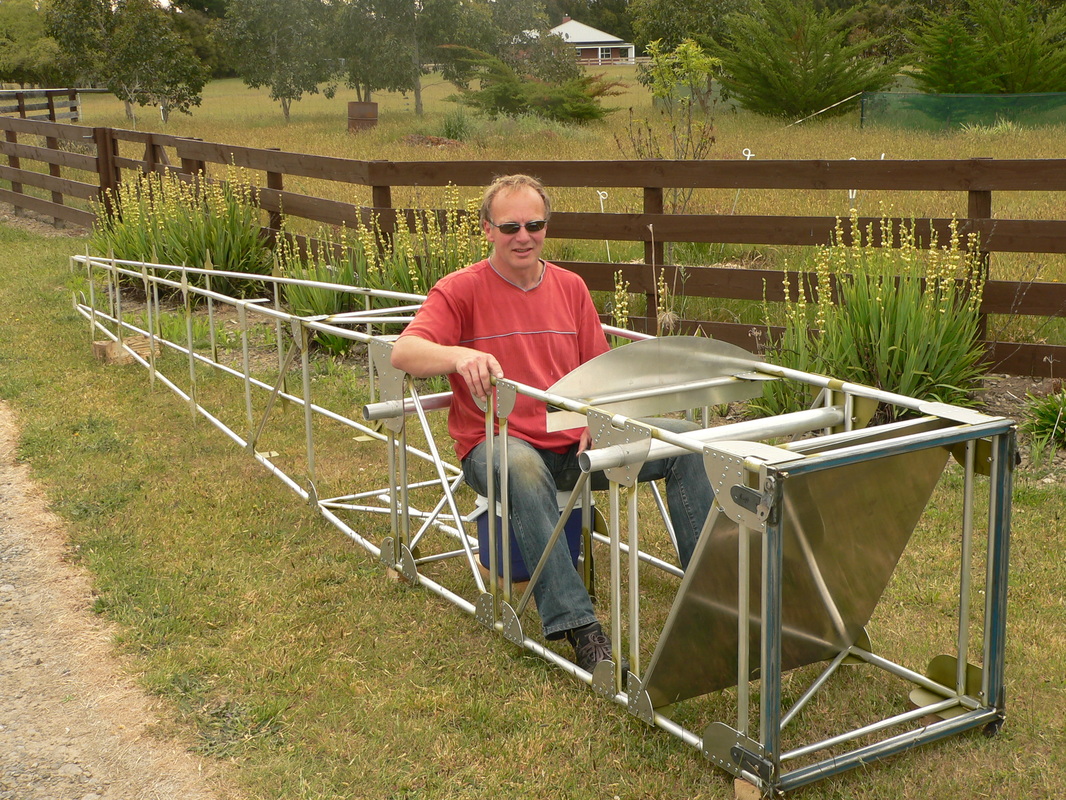
Finished all of the landing gear. Getting the front of the fuselage ready for the move into the shed.
Going to do some more work on the fuselage now, before finalizing the landing gear..........
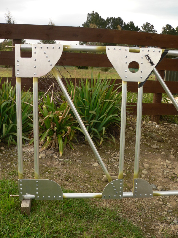
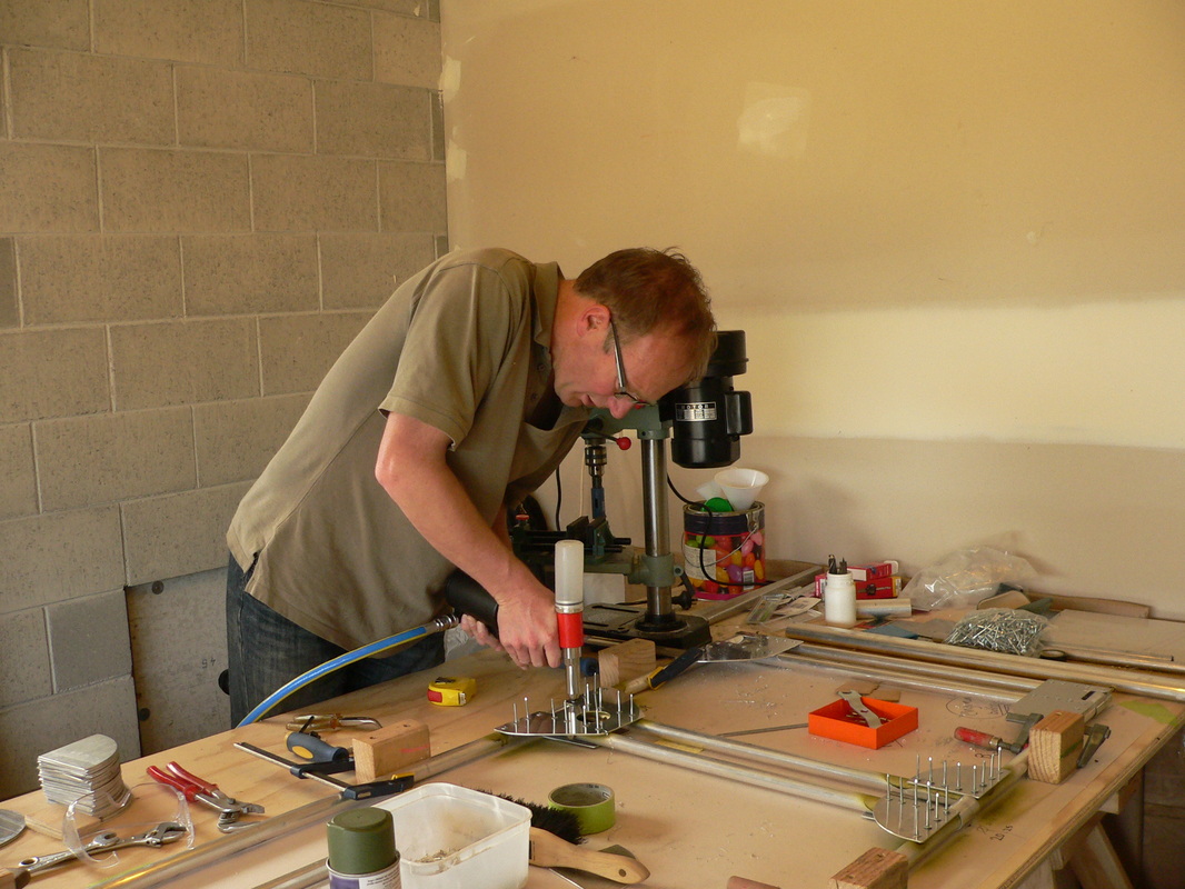
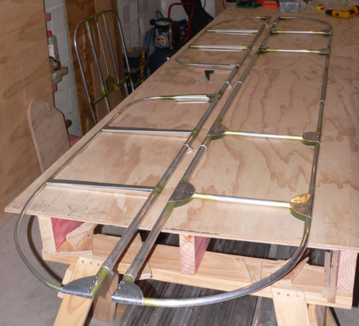
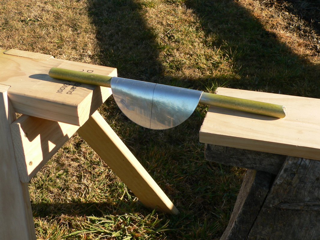
Spend a few hours this weekend on the landing gear.
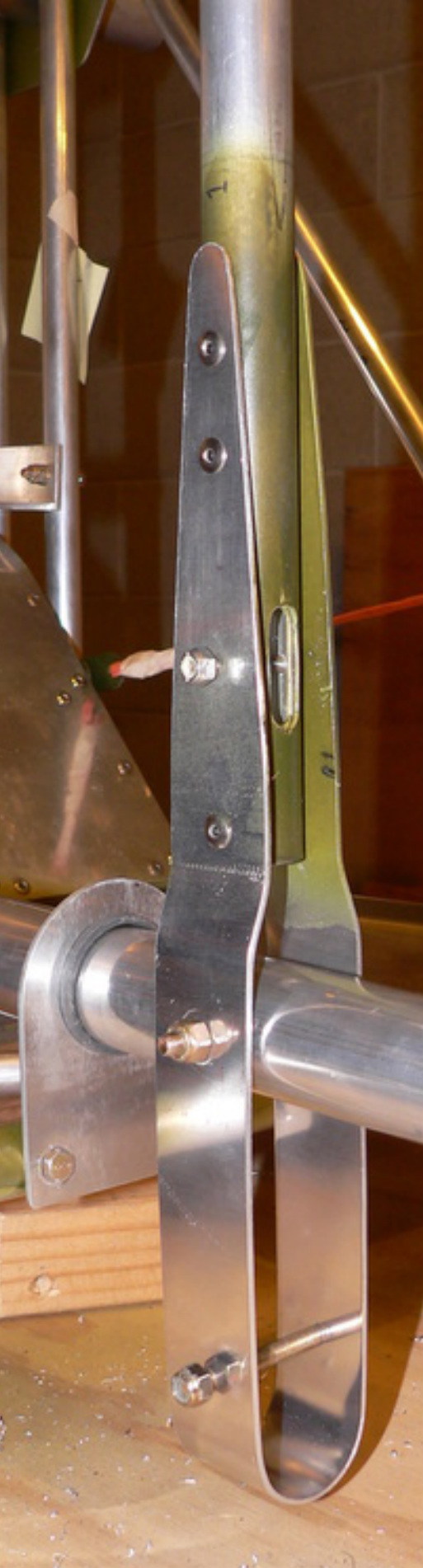
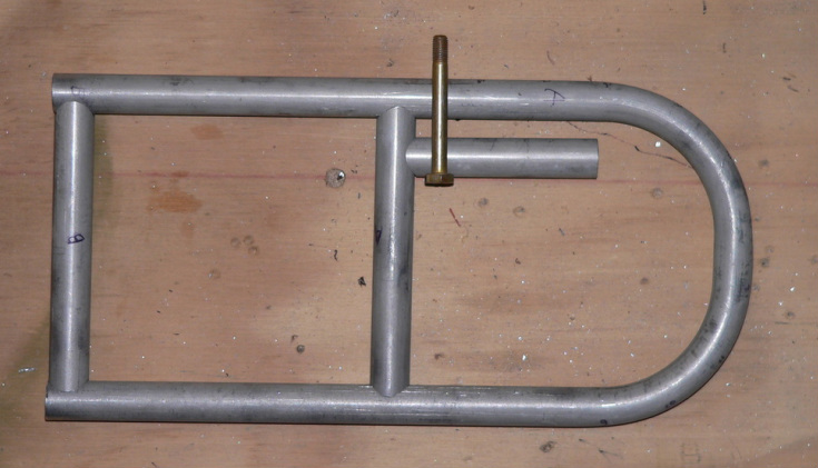
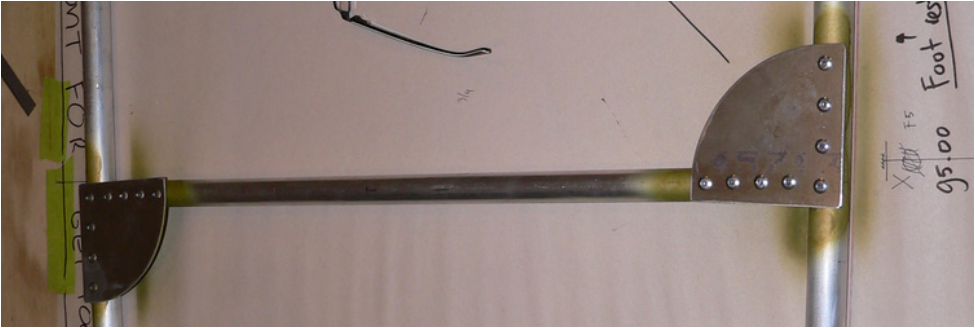
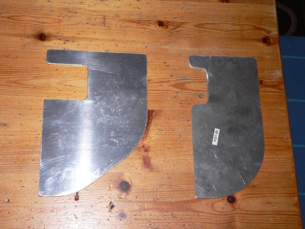
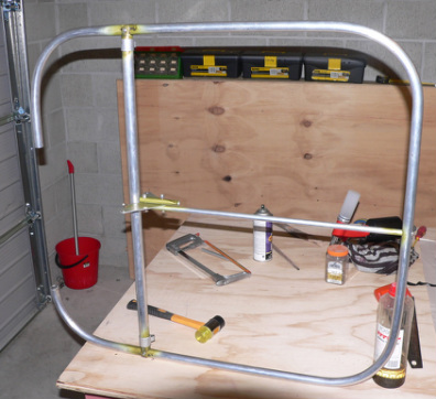
Finished the 2 forks, and started with the connections from the bottom of the fork, back up to the slider.
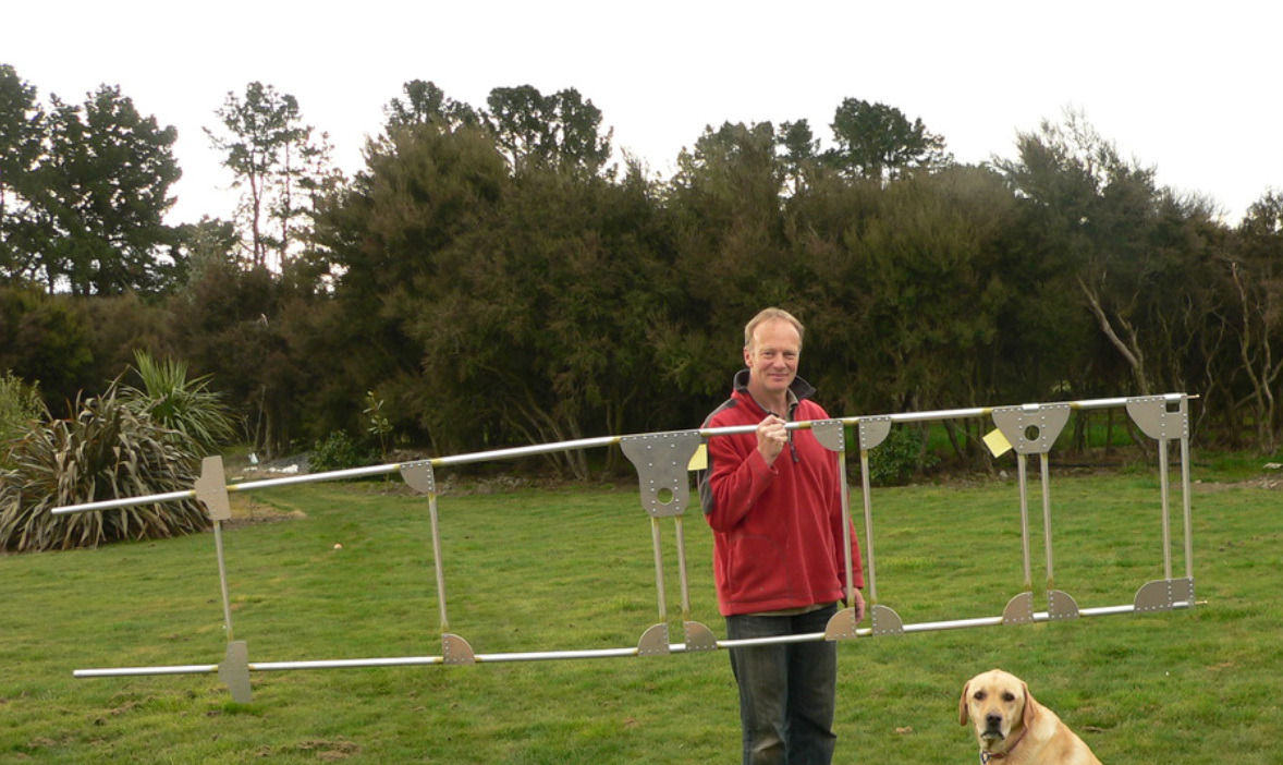
I might get some tires this week, so that I can roll the front fuselage out of the garage next weekend. Its all getting a bit heavier now with the landing gear almost completely in place !
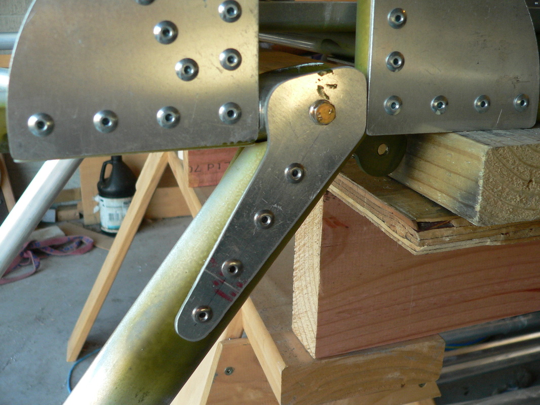
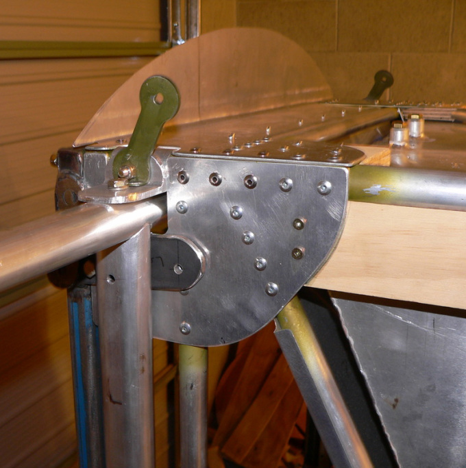
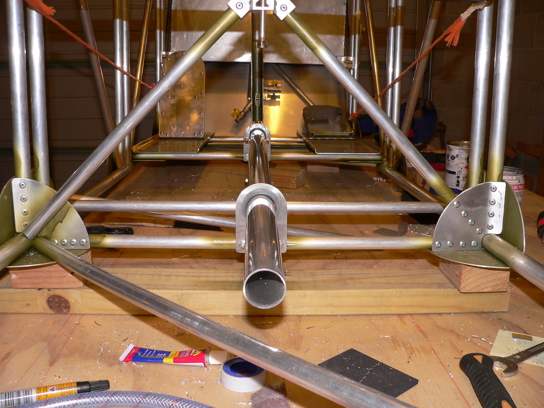
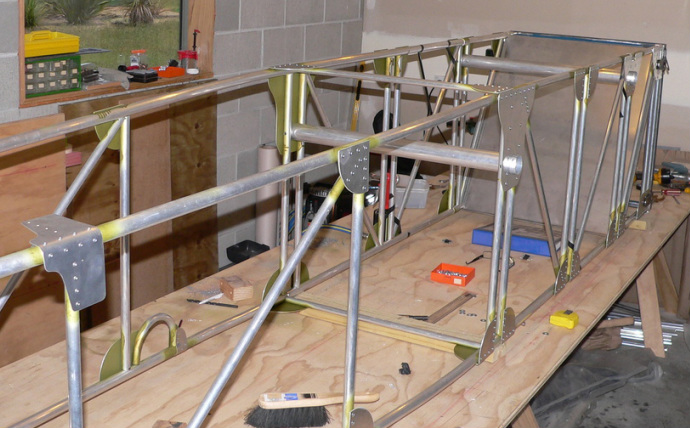
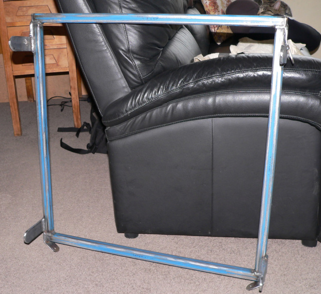
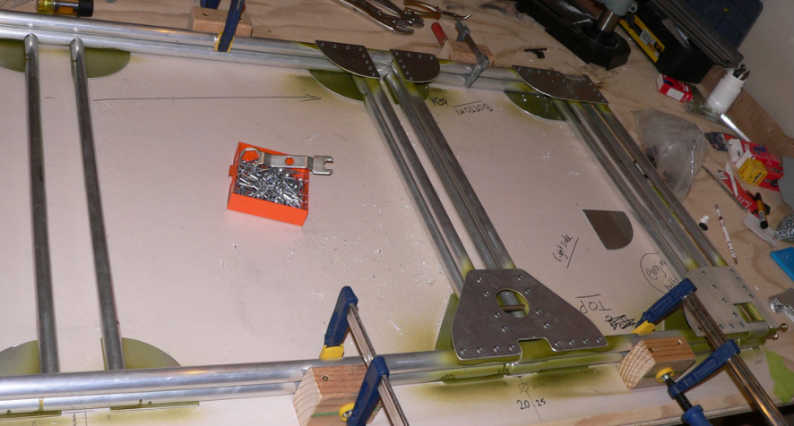
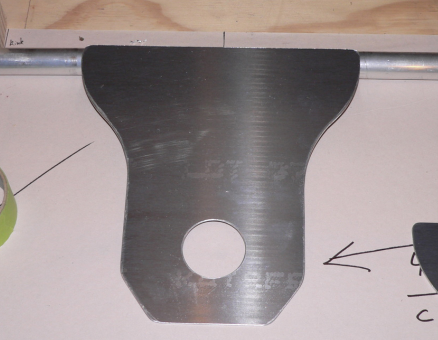
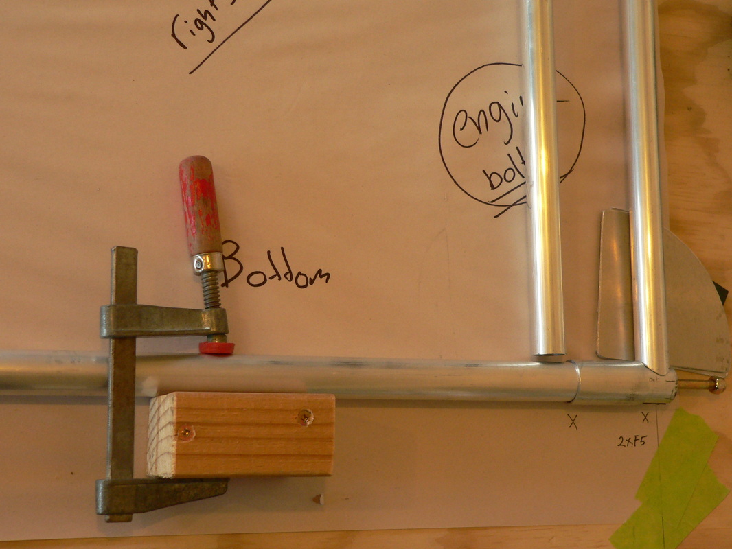
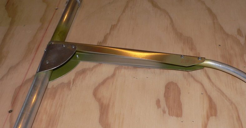
All the brackets done for connecting the bottom horizontal bar.
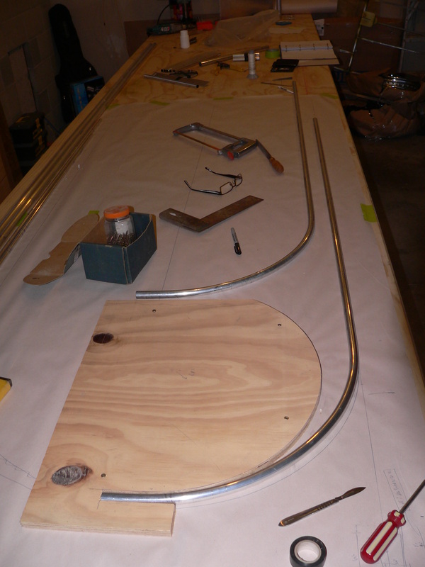
Also the tangs for bracing and lift wires.
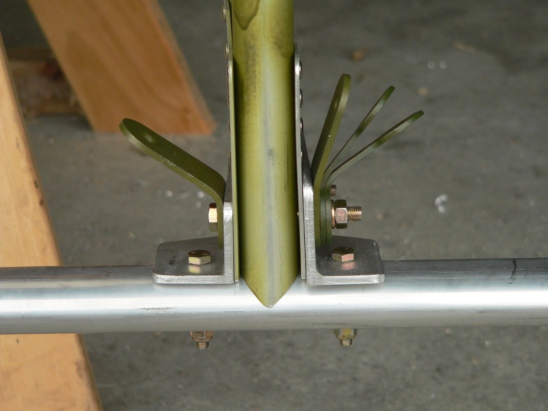
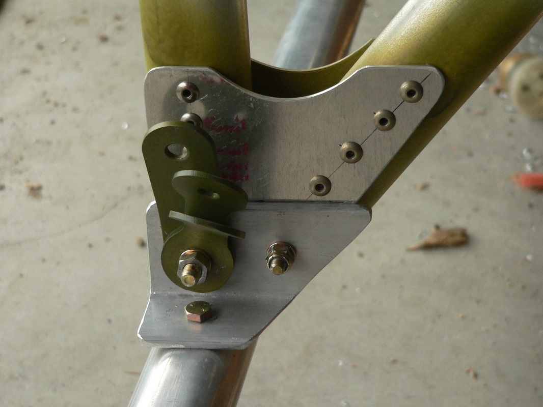
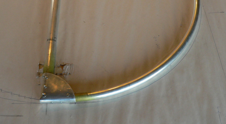
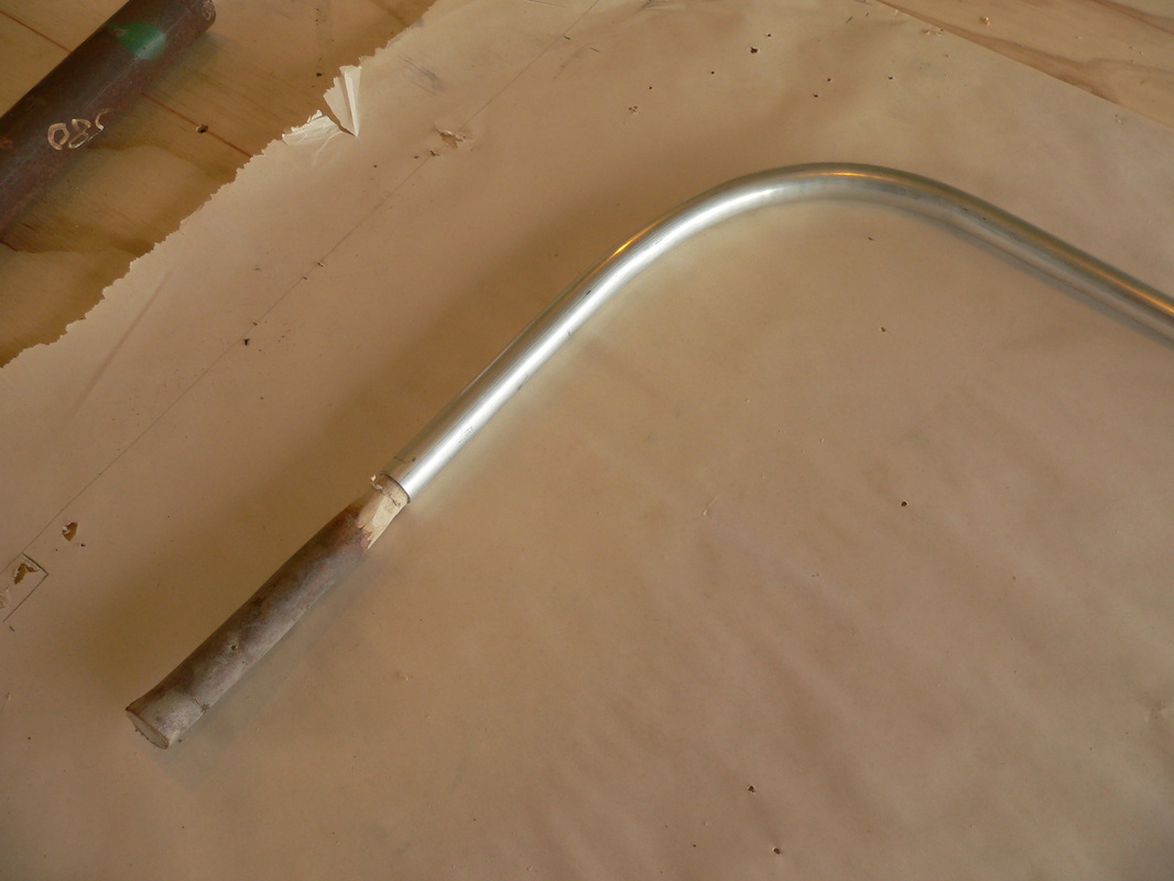
And the beginning of the "fork" that holds the wheel.
Yes made one bracket, three to go.
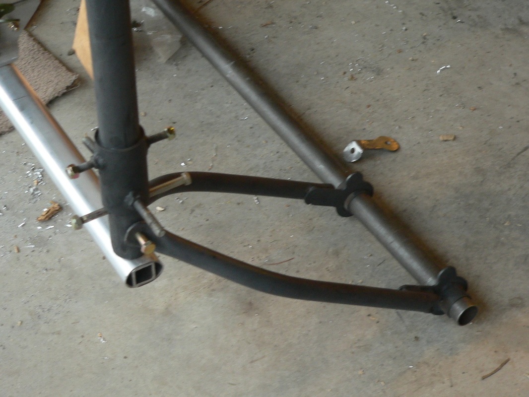
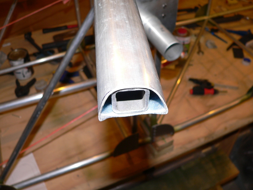
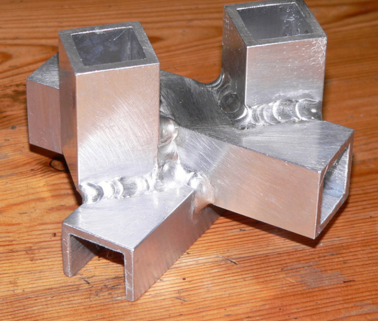
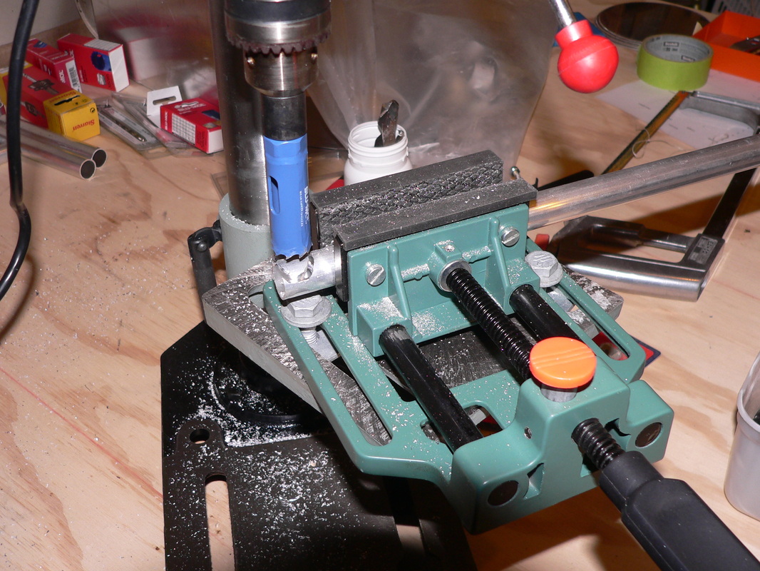
Spent 2 hours, but felt like it was all day, banging the 1" square tube inside the bottom oval tube.
But with the help of Rutger, my 12 year old son it all went a bit easier.
The problem was that the tube had been squashed a bit to much by Robert. But its all looking good now !
Next some brackets to make the connection (see below) between bottom tube and two tubes going up.
Look look !!!!
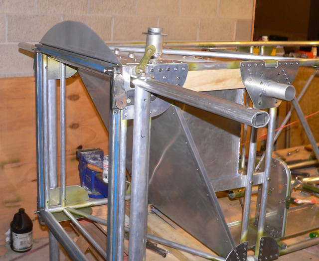
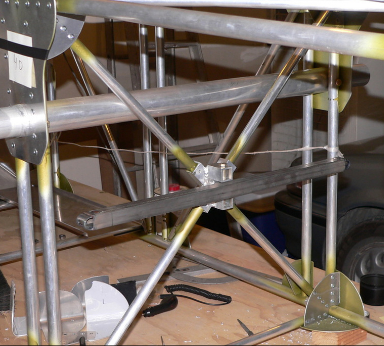
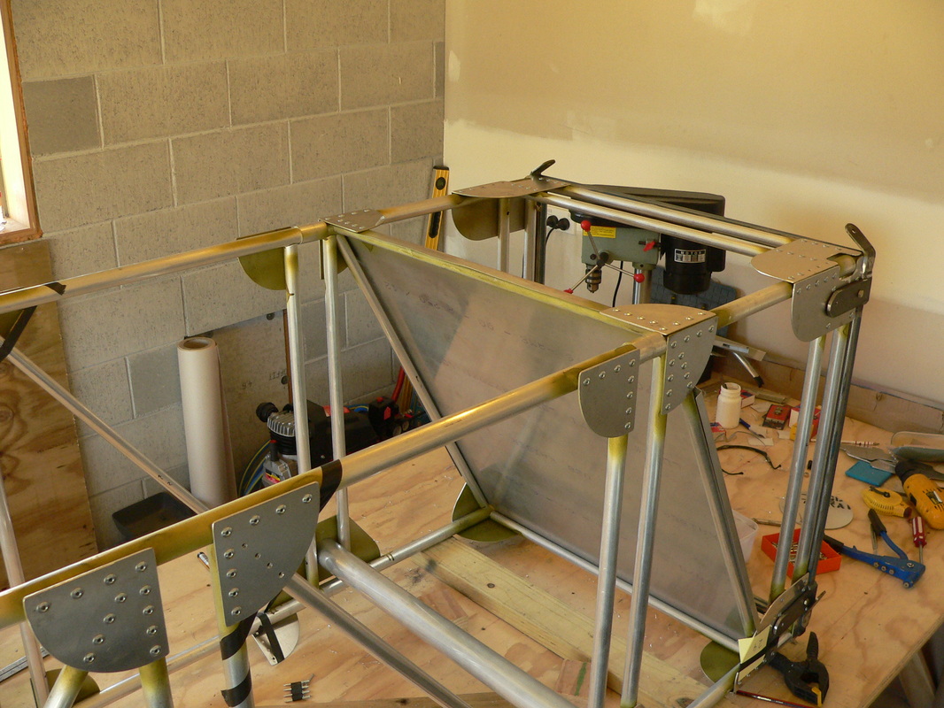
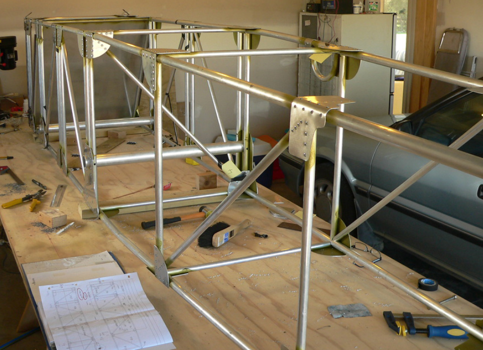
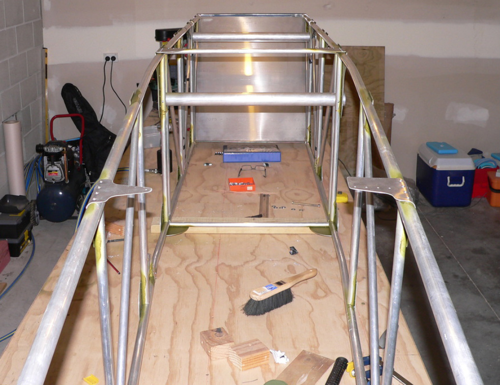
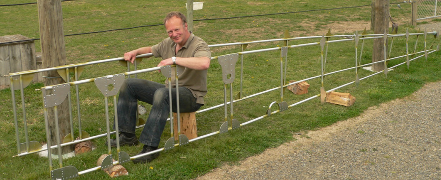
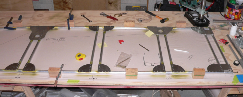
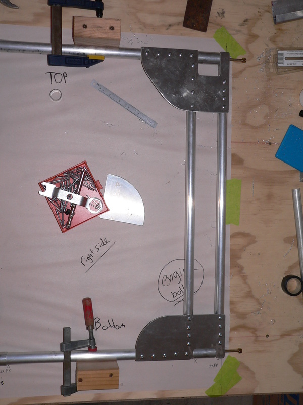
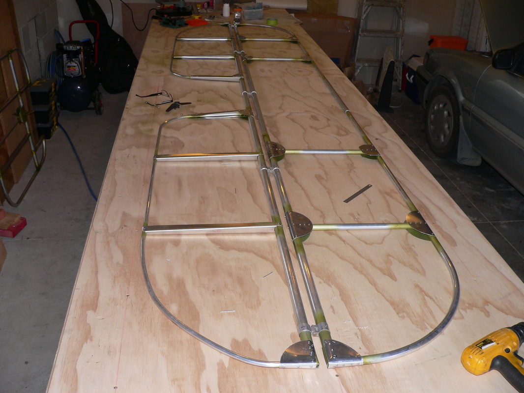
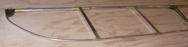
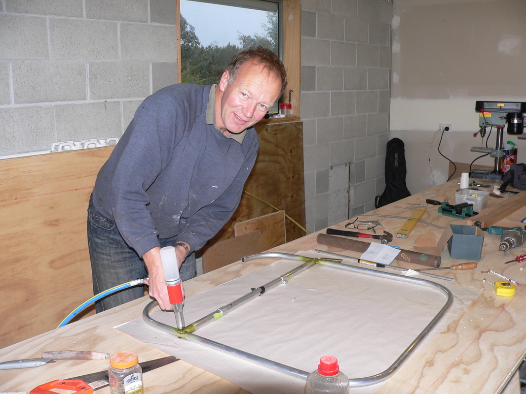
Today I spend 7 hours fitting the bracing tubes, see below. I slowly worked my way through the bits for this. Went really well, and really happy with it 🙂
Slowly this box of tubes is starting to look like a plane!
A real plane, wow !! 🙂
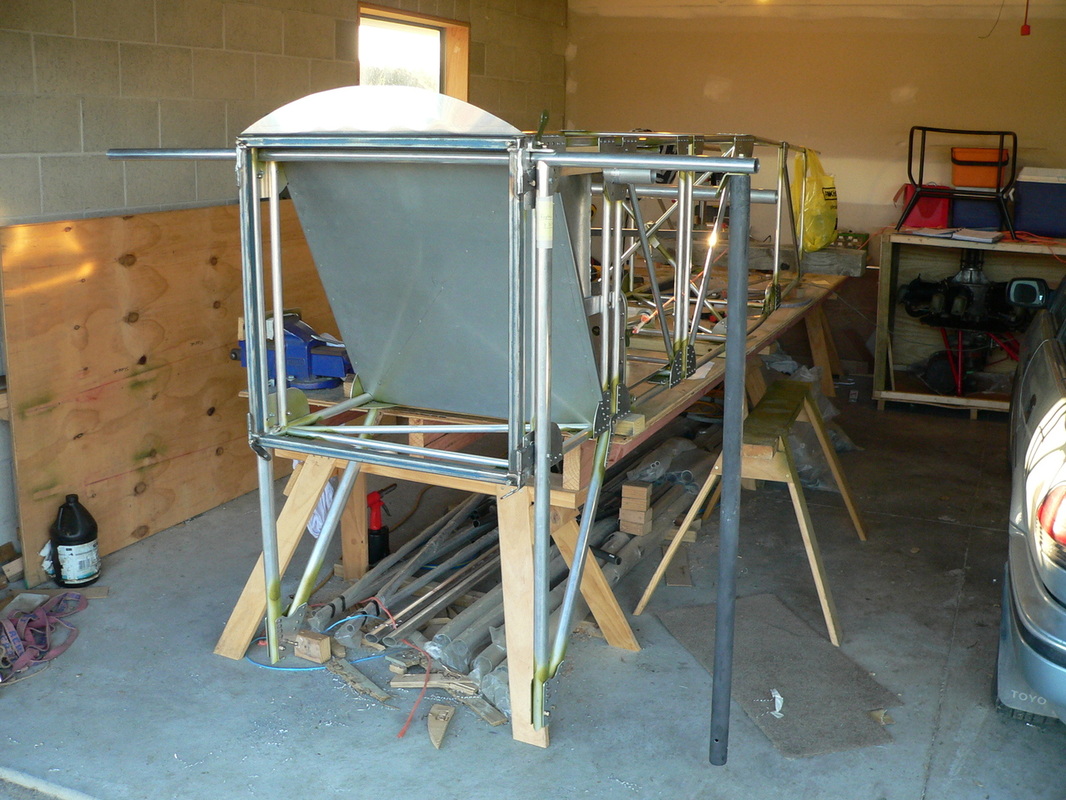
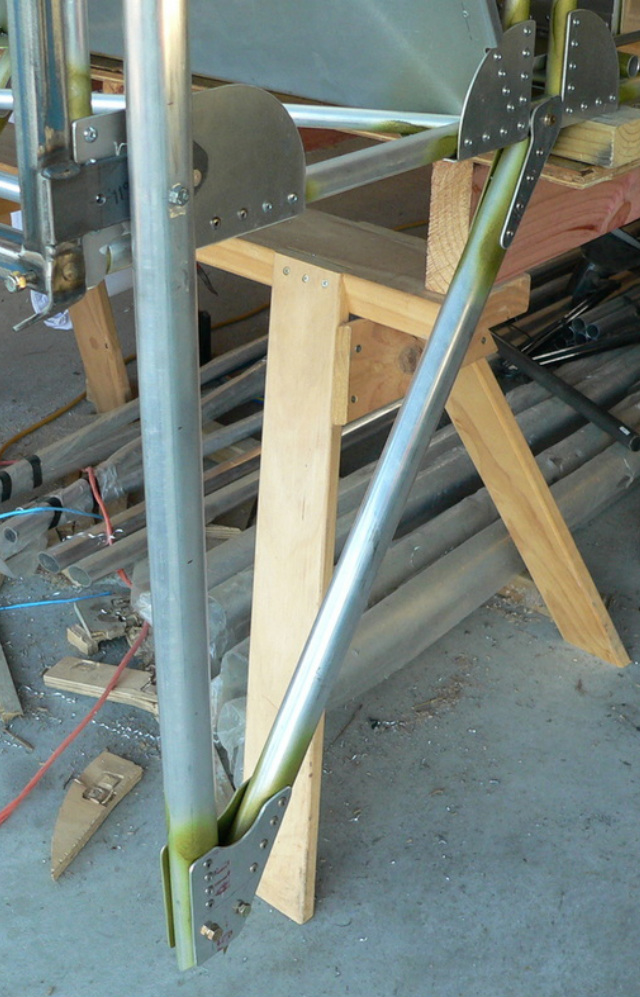
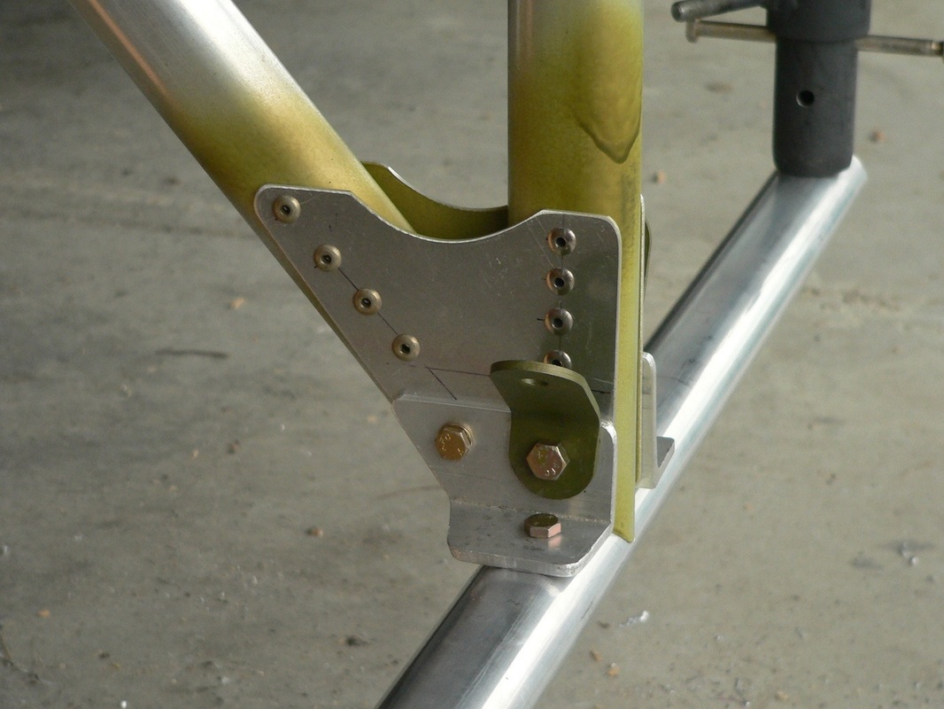
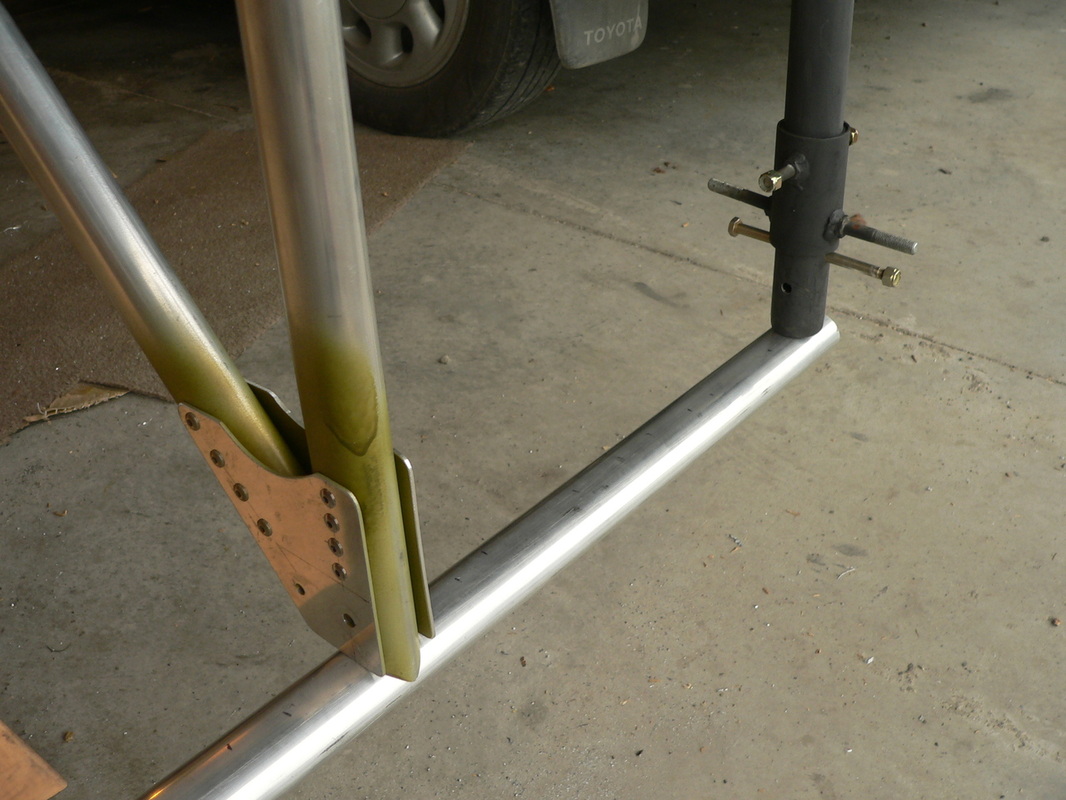
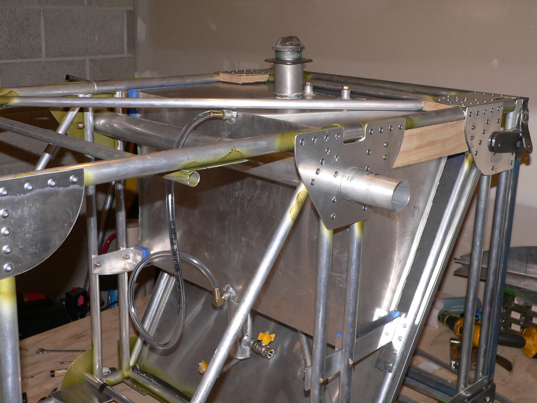
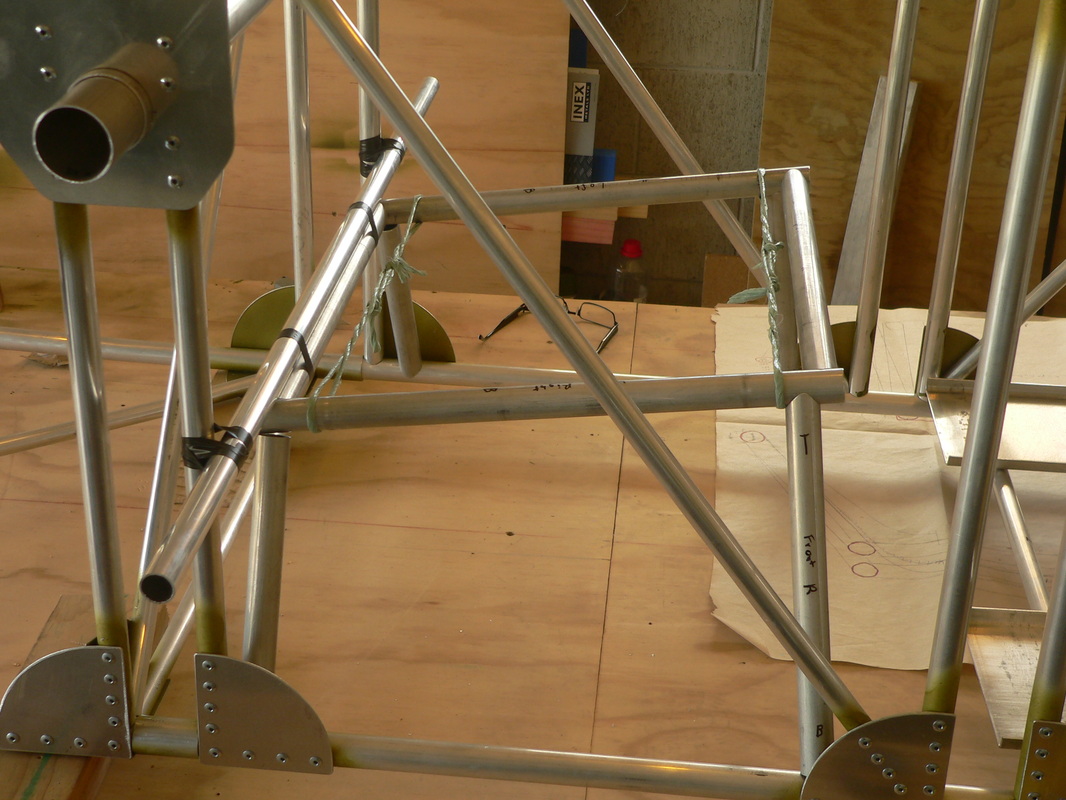
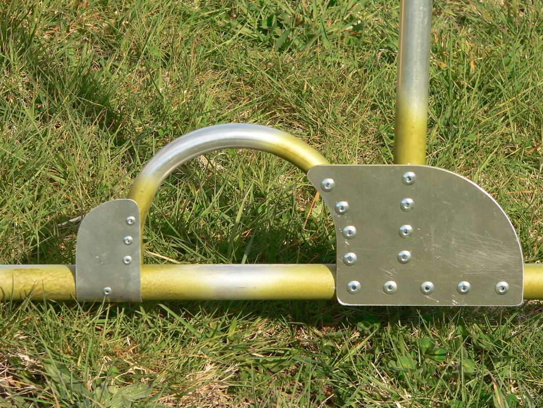
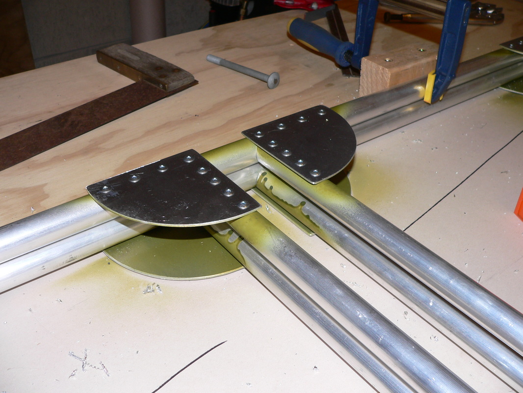
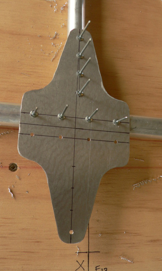
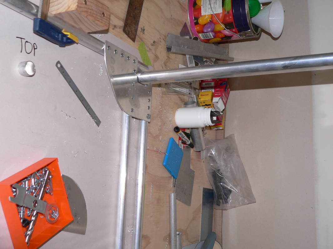
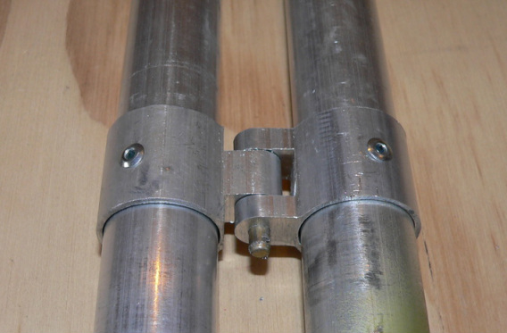
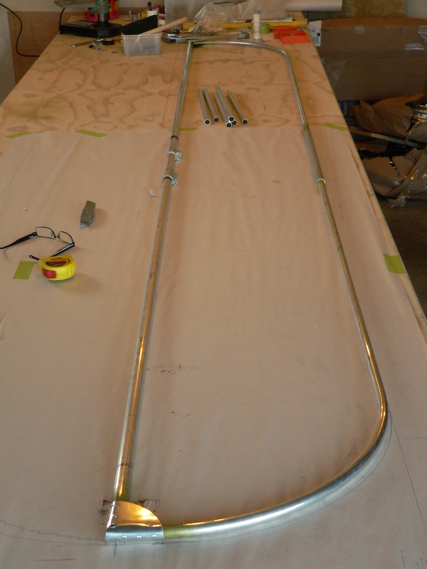
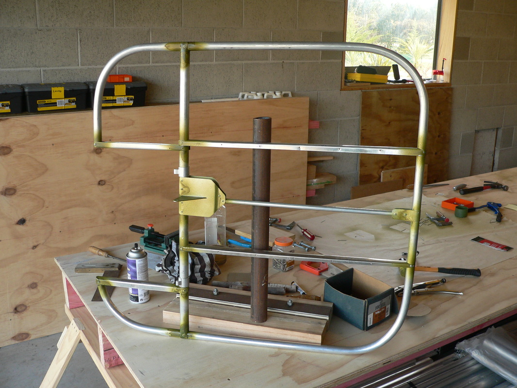
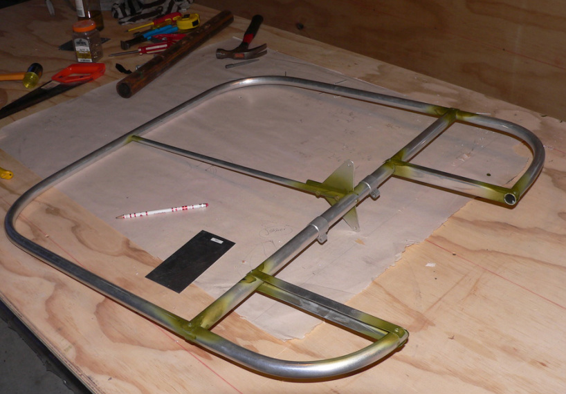
Below the tang for the diagonal brace that supports the weight of the plane "going into the wheels".
Also below, the dark grey round 2" tube , part of the suspension of the wheels.
Above, the bracing fixed into the bottom longeron, and below the tong for bracing the lift structure.
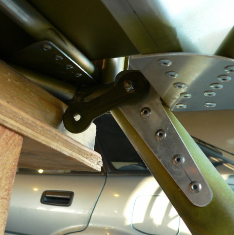
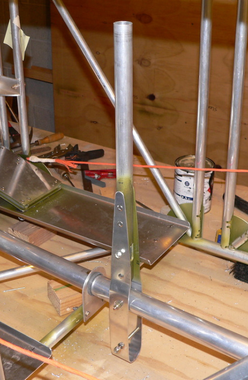
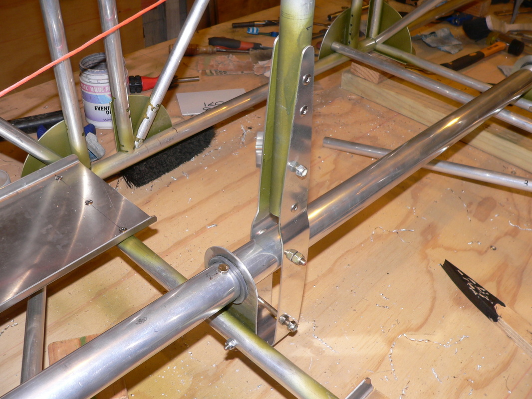
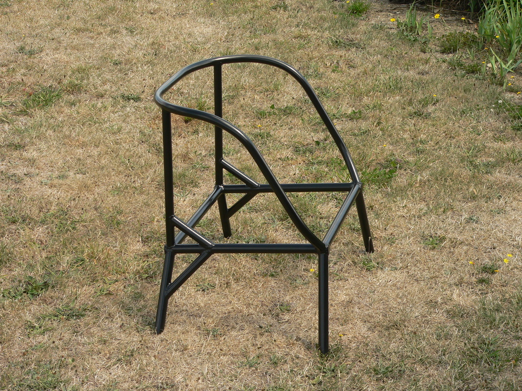
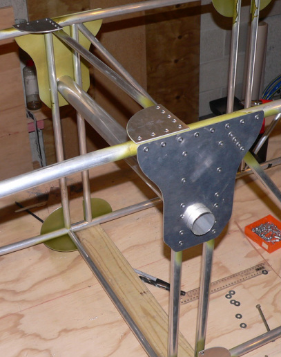
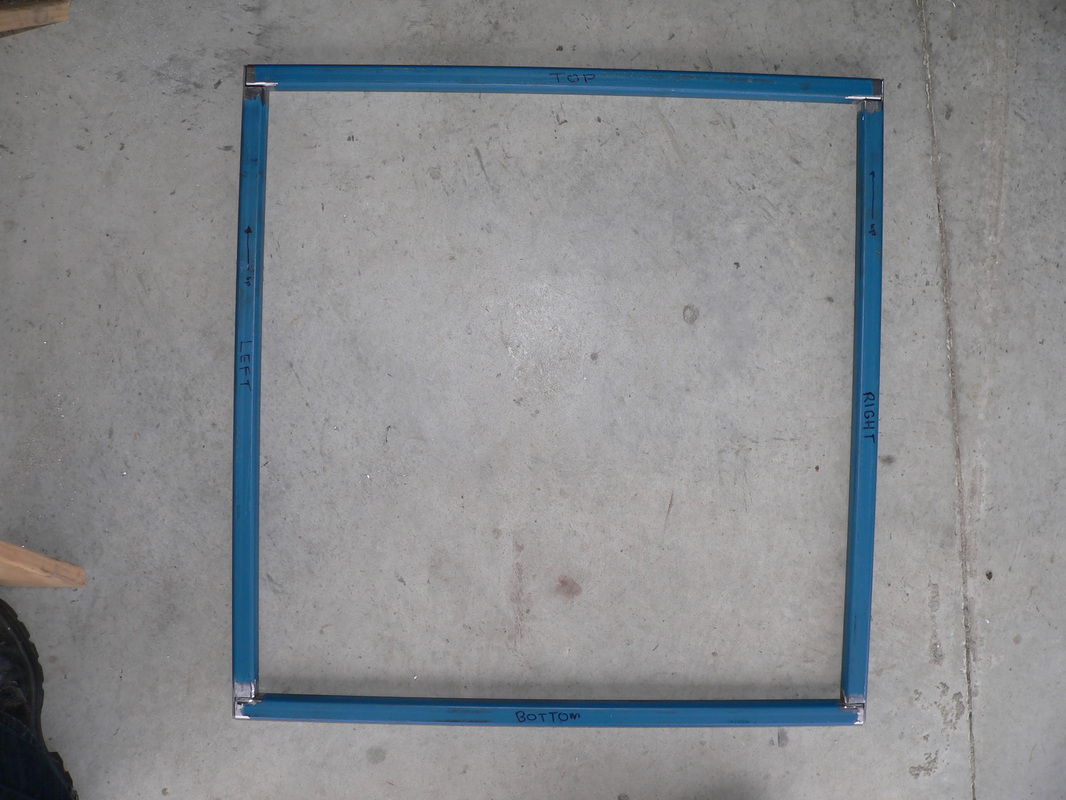
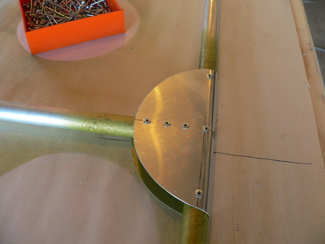
Ready to mount the bracket that connects the bottom horizontal tube, completing the "landing gear frame".
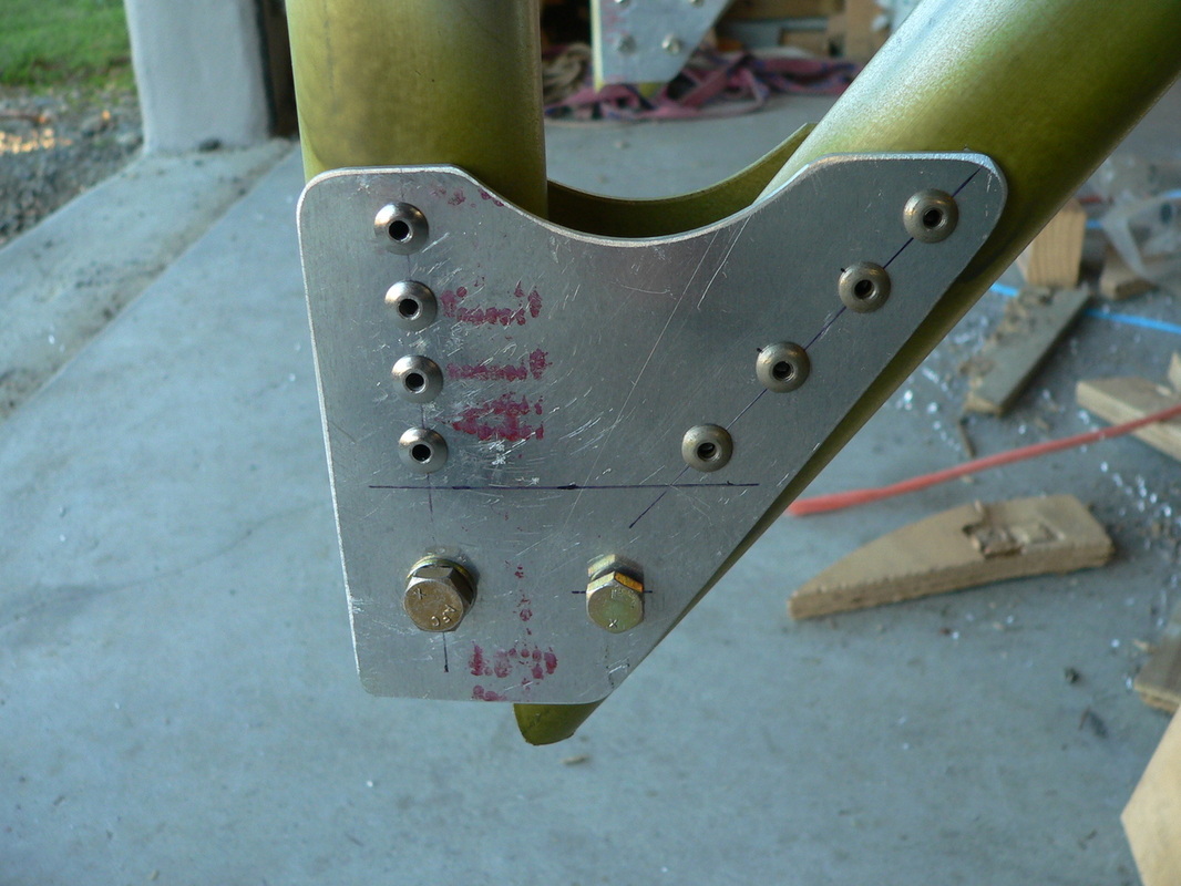
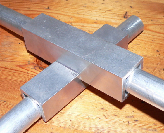
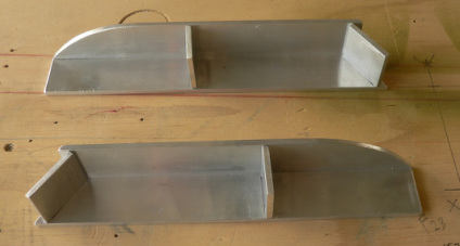
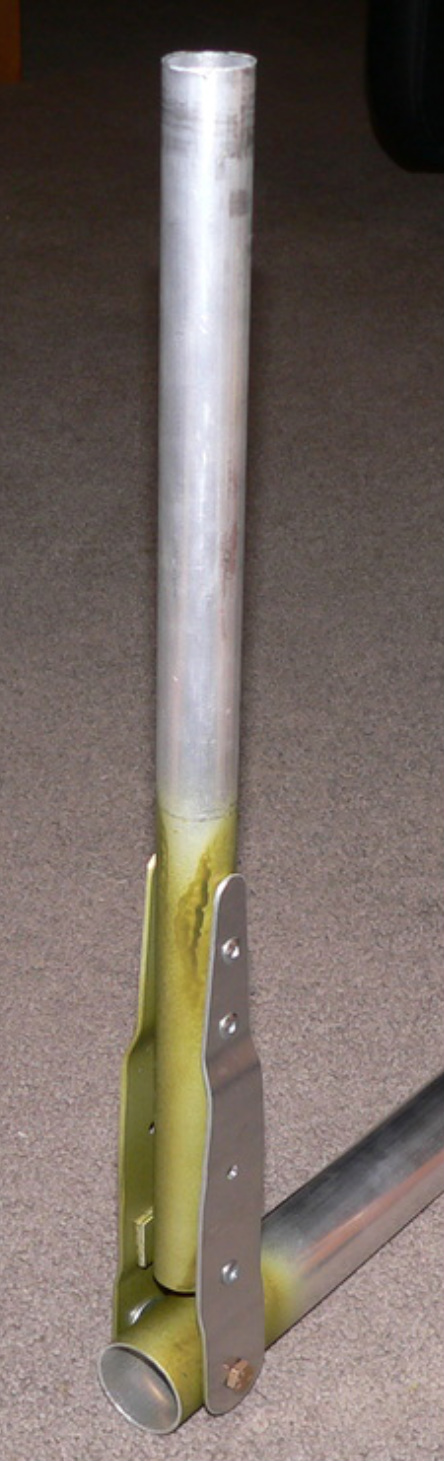
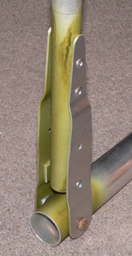
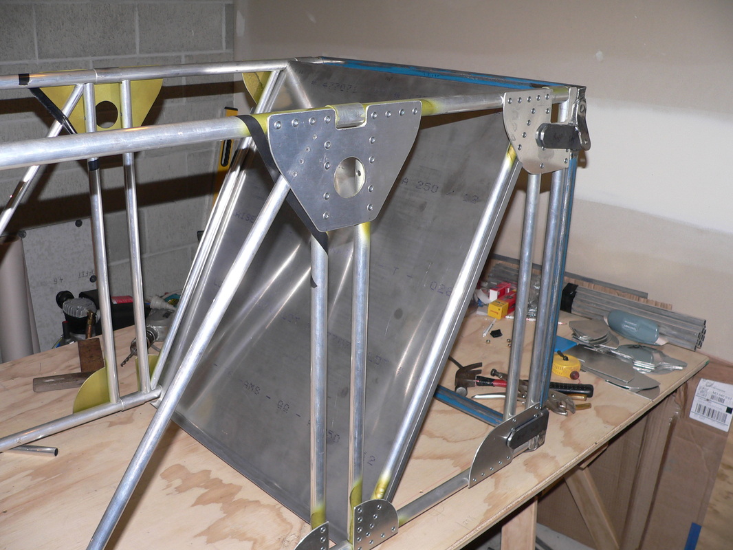
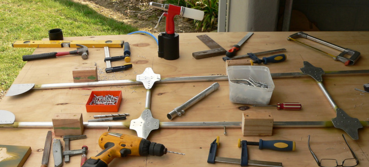
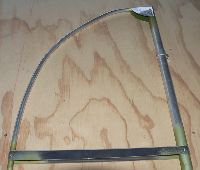
Here are two photos of the first few bits of the landing gear. All fitting perfectly 🙂
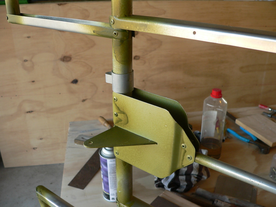
The "green" tang shown, pointing up, is for bracing the cabine.
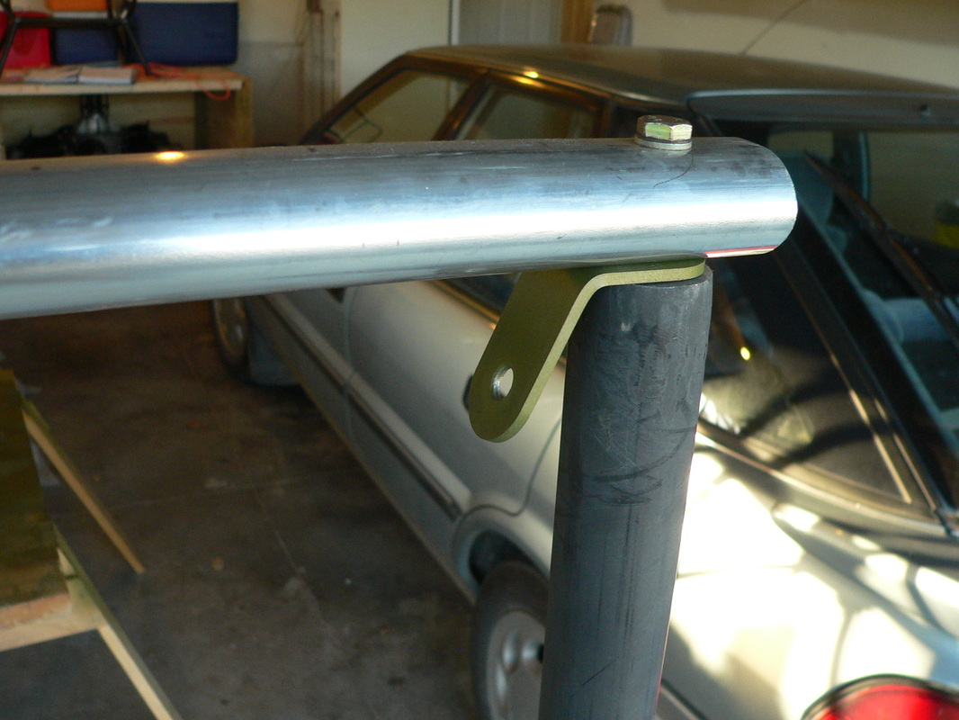
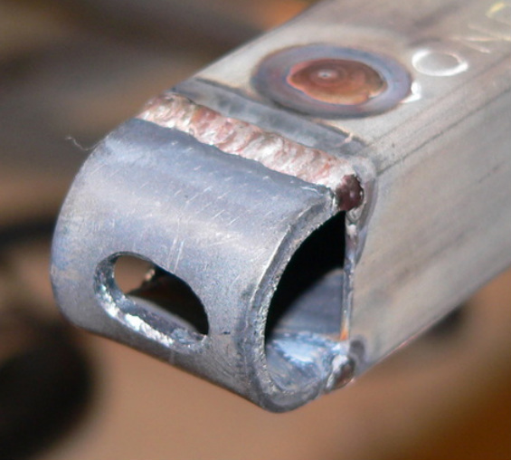
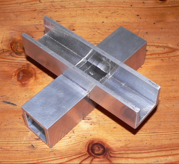
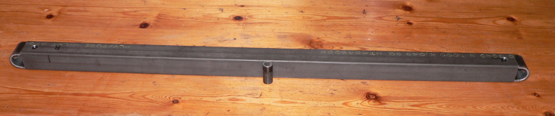
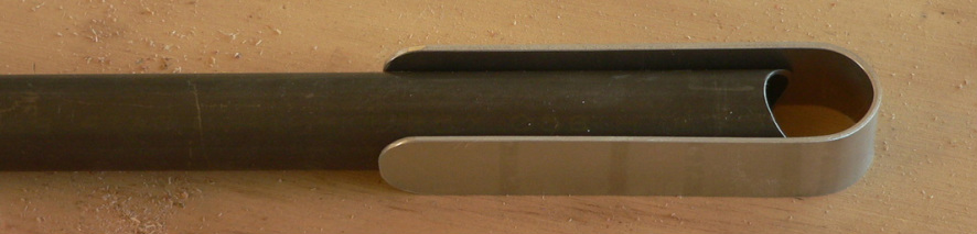
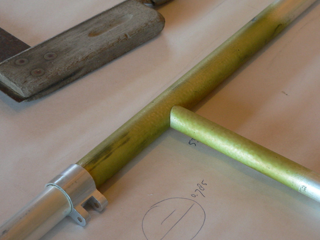
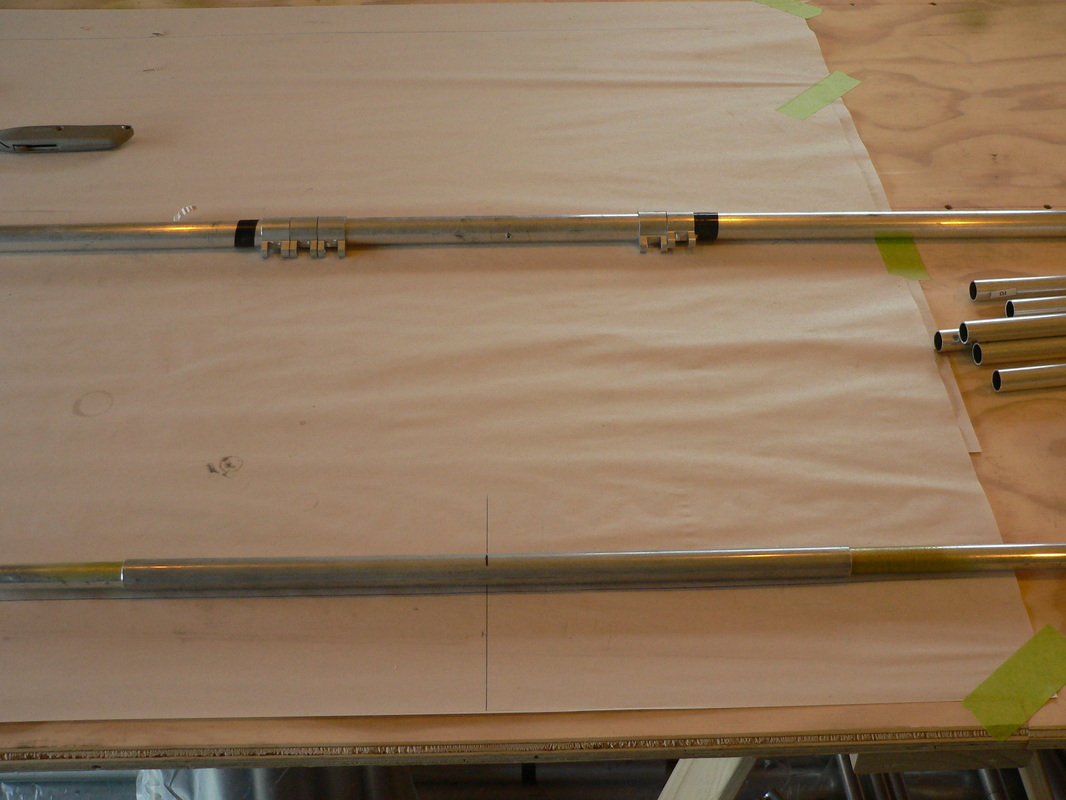
The top horizontal tube for the fuselage that's been ovalized with a 1" square steel tube inside.
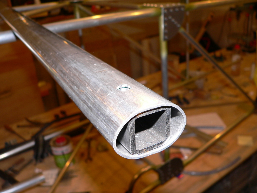
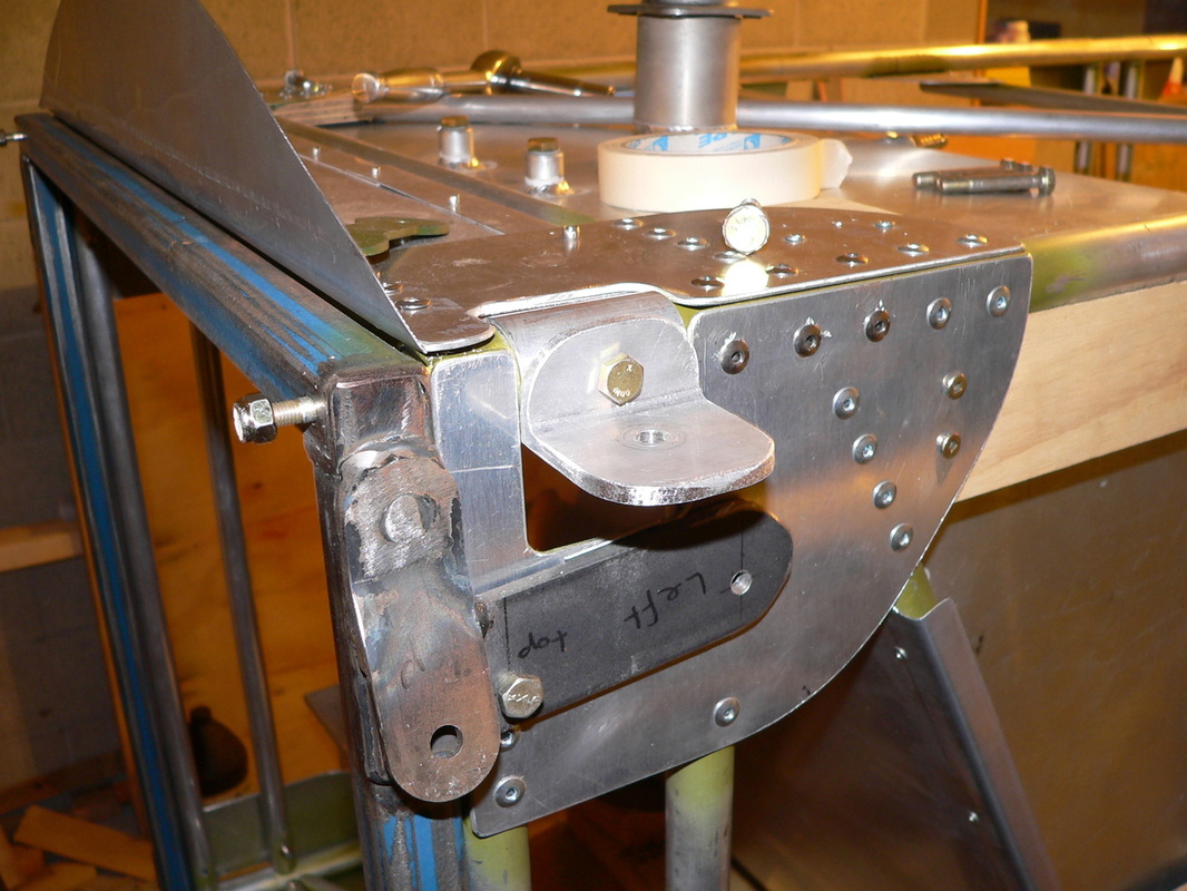
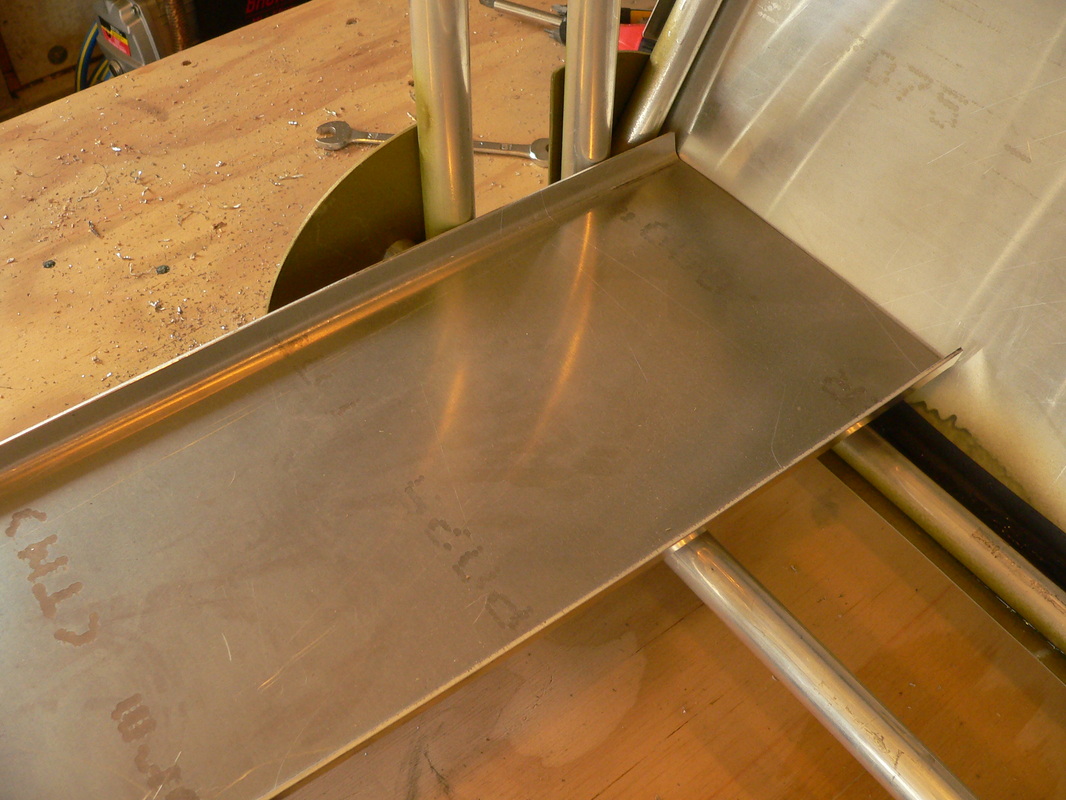
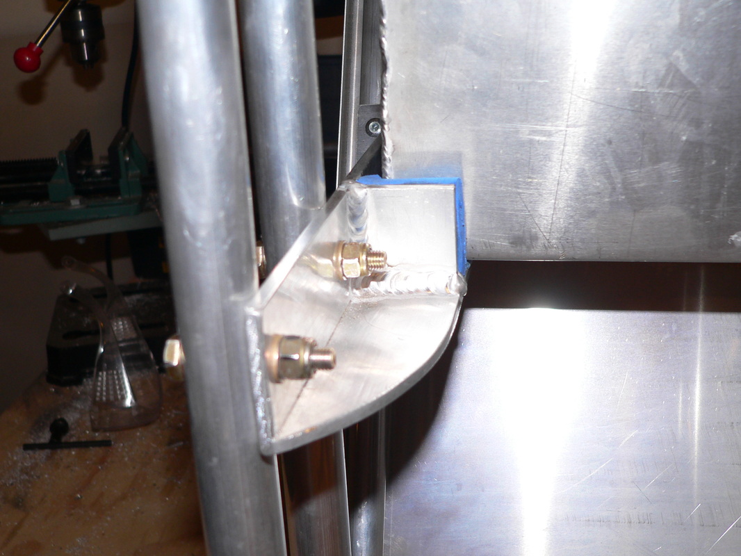
The top of the vertical tube that will be mounted into the top horizontal tube and against the fuselage. It also has a 1" square steel tube in it with a AN5 nut welded inside.

Below the bottom of this vertical tube.
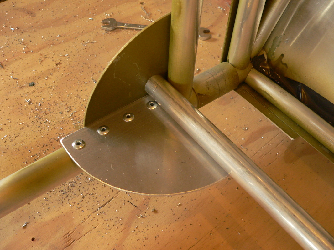
And the bracket that's used to fix the top horizontal tube and the vertical tube into place.
More photo's in the next few days, in case you're all confused......
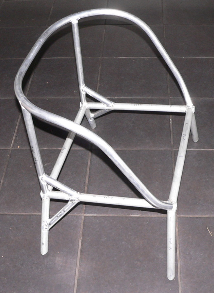
No photos to show about the work done so far, but have done a lot of preparations.
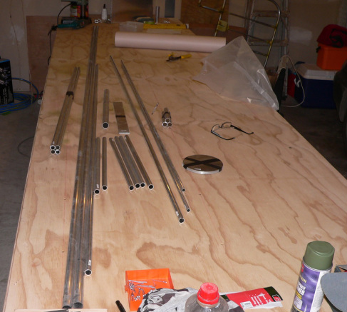
The main landing gear frame consists of 6 tubes. Four of them are ovalized aluminium tubes with a piece of 1 " square steel pipe inside.
Drilled a lot of holes, getting everything ready for assembly. You will be impressed in the next few days, when I can show some photos !! 🙂
Starting to work my way through the bits and pieces for the landing gear now, after I finished as much as I can on the front half of the fuselage, before moving from the garage into the shed.
Hope to show some evidence soon !!!! 🙂
Worked on the control stick this weekend.
The torque tube (horizontal tube, the stick is mounted on) still needs to be cut to the right length.
The two elevator control cables will be fixed to the two bolts shown in the left photo, one below and one above the pivot point of the control stick.
The back of the torque tube still needs the bell crank that is going to move the ailerons, but I will add that when the wings with the ailerons are done. So that's still a little while away.
I am not adding the back part of the fuselage yet, because I want to do as much as possible in the garage which is not long enough for the whole fuselage, so that will have to wait till I move into the shed just 50m away from the house 🙂
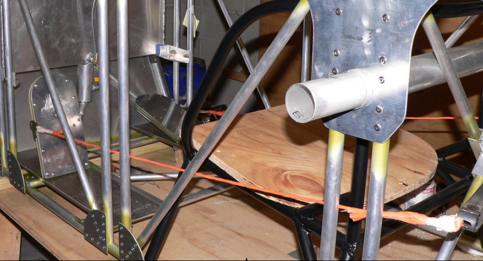
The piece of 2" tube going to the left (forward) of the control stick is now cut of, to give me a "clear view down" !!!
There won't be a floor so, can keep an eye on what's below me 🙂
Next is going to be the LANDING GEAR. Wow making progress I think.
Almost done with the rudder control pedals, next will be fixing them to the floor boards.
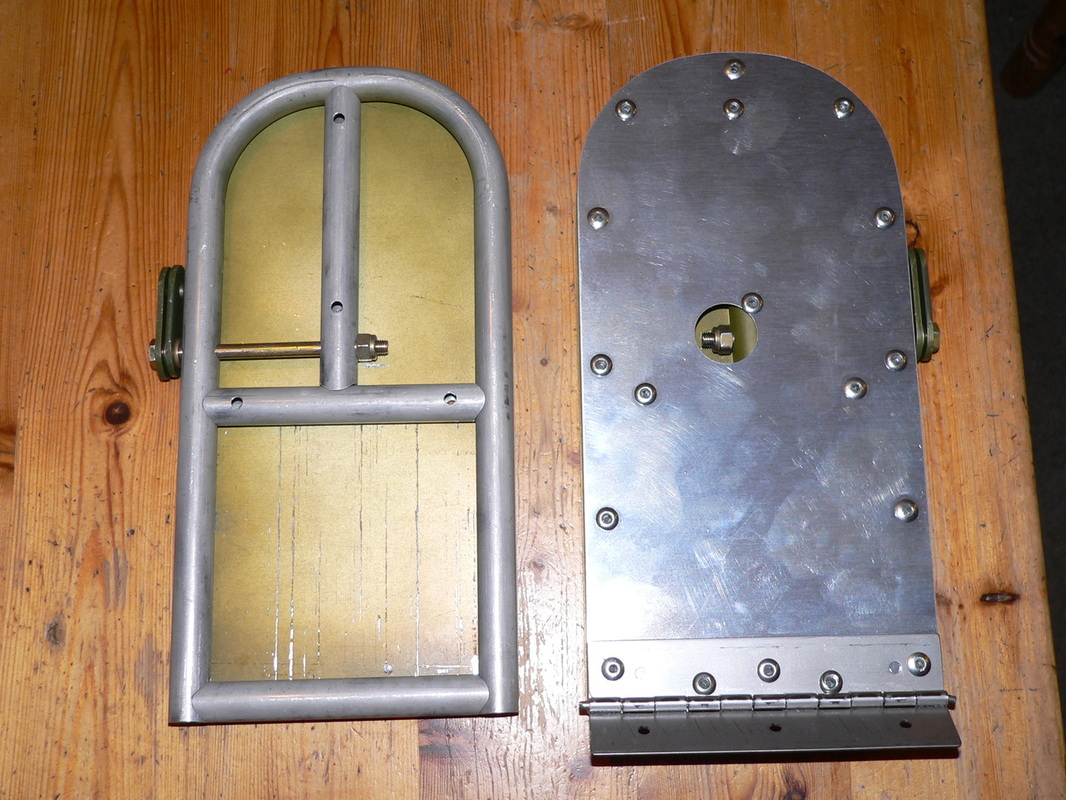
What you see here is the back, with an access hole to the nut, just in case……
The two tangs shown on the side are used for:
Below are the pedals in position and fixed to the floor boards. Have used some string for now to see how they work with the walking bar.
Feels good I think ! 🙂
Here it is.
Front completely finished, except for the top.
Have been riveting the firewall in place tonight, and attaching the curved top on the front, before I continue with the pedals. Suddenly it starts to look more complete.
Will take picture tomorrow night. The fuselage is upside down at the moment.
Got a piano hinge today and cut two 5.5" bits (the width of the pedal) for the two hinges for the pedals. That all looks good. Also I started cutting and shaping aluminium sheet to go on both sides of the pedal frame. So yes starting to look like a real one 🙂
Also I have changed the tubing a bit. The short bit supporting the bolt is now gone, and replaced by a longer one going all the way to the top of the pedal, and positioned in the centre. The bolt is a bit longer as well. Will show you soon !
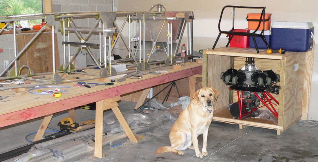
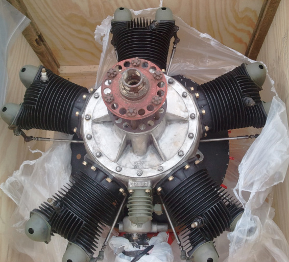
Well the engine is in it's final resting place for a little while now, as close as I could get it to it's fuselage 🙂
To see how the engine restoration is going, click here Engine restoration.
The beginning of the rudder pedals.
Tubing for one done, next one soon....
This frame of 5/8" tube will be covered on both sides with 2021T3 aluminium sheet.
It will have a hinge at the bottom of the pedal (is left on the photo). The cables will be connected on the AN4 bolt. The extra bit of short piece tube supporting the bolt will give it extra strength.
YES
the engine has arrived !!!!!!
Looks good Jack :-)
Hi Gerty,
Awesome – can't wait for you to do some aerobatics – give it heaps.
Finally riveted the 2 cross tubes and the one diagonal cross tub that I mentioned on Sat 16 Mar.
So with the floor boards sitting on the two cross tubes, I can start thinking about the 2 pedals and how they are going to be mounted there on those 2 floor boards.
Done the walking bar !!!
Next job, the pedals.... But before that a few more cross tubes.
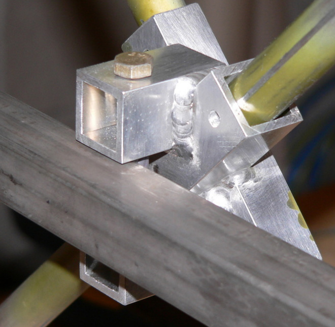
Here is the whole bracket welded together.
The two bits on the top are going to support the walking bar. So next I need to drill a hole through the 4 walls !
Ik heb even gekeken naar jouw droom. Geweldig zeg!
Komen dromen toch ooit uit!
Veel succes ermee. Groetjes Anja.
I had a look at your dream. Great!
So dreams do come true!
Good luck with that. Greetings Anja.
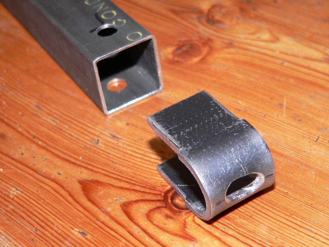
Here are 2 bits that need to be welded first for the "thing" that will be positioned on the two diagonal cross tubes just behind the back carry through. One bit is open so it fits over the first existing diagonal. The second diagonal slides through the second bit.
Once its welded, I need to make two more bits to support the walking bar.
When he told me he ordered the rudder to start building his Bleriot, he said:
You got me motivated and your website has been fantastic!
Here is the walking bar, ready to be welded together. The square tube is Chromoly, 1" sq. On the left you see one of the 2 inserts I made to attach the cables to.
The 2 holes you see in the sq tube are there for creating extra welding "spot" to make sure the insert never gets out again! The bar is going to pivot around the tube you see in the middle of the bar.
Next thing I will be making is the "thing" that is going to hold the bar in place behind the seat.
Just spoke with Robert about this and he normally has cables going from the pedals straight to the rudder, without anything in between.
This means that if a lot of pressure is applied to both pedals, that goes straight to the rudder control horn. Not sure if I like this.
Hmmmm will have a bit of a think about this. Still think I will go ahead and have the walking bar behind the seat.
Added a gusset plate to mount the second diagonal cross tube behind the back carry through to carry the load of the walking bar that I mentioned earlier.
Change of plans.
I need to "wicker" the seat first and then build it into the plane. The gusset plates that are going to hold it are made so I can't get the seat out or in, once those plates are riveted to the bottom longerons.
So I have to finish the seat completely before it goes in.
So while I am looking for someone to do that seat, or maybe I might do it myself, I am working on the rudder controls.
What I am going to do is the following:
I am constructing a walking bar of Chromoly, behind the seat with two cables going to the back to control the rudder. And from the walking bar I have two cables going forward going to two pedals. This way I can put a lot of pressure on both pedals without damaging anything. Working on the bar construction first.
The problem is that that bar can't be at the bottom as it will be in the way for the aileron control. So I have a cunning plan to mount it halfway up to the diagonal cross tube just behind the seat and just behind the back carry through, if that makes sense. In fact I will have two diagonal cross tubes, one going top left to bottom right and the other one top right to bottom left. And at the junction, I am making a little welded aluminium construction that is going to hold the walking bar.
Will show you some photos soon.
I was just looking at your site again. I've got a grin on my face that damn near wraps around my head.
I'm proud of your efforts buddy!
Not so good news: Container only just left Los Angeles yesterday after its been hold up by the US customs people.
The container is on the Itajai Express. Expected to arrive on the 7th next month.
Oh well just have to wait a little longer 🙂

Made the last gusset plate that's holding the seat tonight.
Soon I will start riveting bits together and add a few photos here !
No photos today, but I did 5 gusset plates of the 6 that are going to hold the seat and 2 cross tubes.
Installed the 4 gusset plates for the cross tubes today that are going to support the floor boards and maybe the rudder controls. I have not fixed the cross tubes yet.
I am going to wait with that until I know how I am going to do the rudder controls. Two pedals or the rudder control bar…..
Tightened up the 4 AN5 bolts that go through the 2" carry through, to lock them into the fuselage frame. You can just see one of them in the big photo above, on the left side of the front carry through.
You might remember that the 2 vertical tubes on each side of the carry through have a second tube inside, to make it all nice and strong !!!
The same 4 bolts also hold the four 1 and 7/8" inserts in place that now stick out on each side of the fuselage (again see big photo above for the front right insert). The 2" wing spars will slide over these when attached to the fuselage.
Also started with the cross tubes (connecting the left and right side) where the two floor boards go. These cross tubes don't "hang" underneath the bottom 2 longerons, but I am placing them on top. Will show you on Saturday what that is going to look like
And here are some photos:
OK sorry it has been a bit quiet here. Lots of other things happening, but more progress is about to happen.
The welding on the fuel tank and the brackets supporting the tank were done a couple of weeks ago. Tonight I managed to put the tank in position and bolt the brackets in place. Will make a few photo's tomorrow 🙂
Hi there.
Excellent web u got there..
I’m real interested in your project, Nice kit to built with lots of history, and will always turn heads with it..
I assume those yellowish spray on every join on the frame is some kind of rust preventative?? Not that aluminium rust?
Please…LOTS of photo’s of that engine..ignition, carb , rockers. Manifold, etc. LOVE the work u have done!!! Looking forward to the next “reading” of what u are doing there in your garage.
Greetings.
Rudi Fick
South Africa. (Sorry, not into Rugby)
Ps. Engine should be there by now?? It’s not Africa there u know??
Just got the confirmation that the box is in the container and will be here on the 26th of March.
Just a few more weeks !!!!
First coat of primer on it. Wow, looks like a real one !!!! :-)
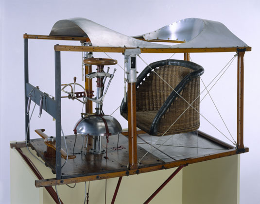
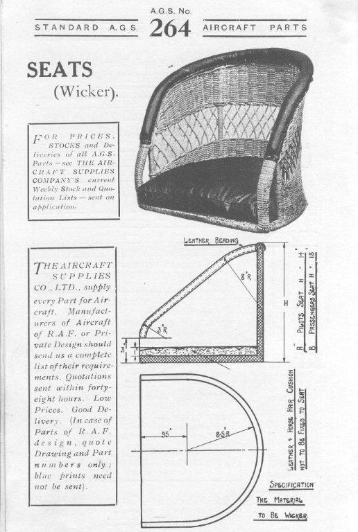
Found this one on the web.
This is in the Science Museum in London. It is very basic but that suits the plane well I think.
What you see here are the original controls used in those days.
Your website looks great and is very informative. Your workmanship looks very good as well. I just saw your last post, the frame for you seat. It looks like you are making very good progress. I'm looking forward to starting my Bleriot adventure.
Message from Jack:
Gert, The trucking company picked up the engine this afternoon!! Hope you get it before too long. Jack
YES, ITS COMING THIS WAY !!!!
Just picked up the frame of the seat from the engineering shop. They welded the seat in two stages. First stage was everything except for top rail and 4 small braces, on the back side, above and below the sitting surface.
The top brace is there to create an opening in the side panel of the seat for the safety belt to go through.
The bottom of the 4 legs have been coped to sit on top of the bottom longeron's
Just spoken with Jack, the guy I bought the engine from.
The engine is ready to be shipped !!!
VERY excited for your Velie - you will have quite some plane!!!
Yesterday and today I did a lot of work on the seat. Bending, coping etc.
Will show you when that's done in the next few days. Very happy with the result.
Waiting for some welding to be done on the fuel tank and the first stage of my seat.
So today I cut the ply that goes on the side of the fuselage. It fits perfectly. Looks a bit strange right now, a bit naked.
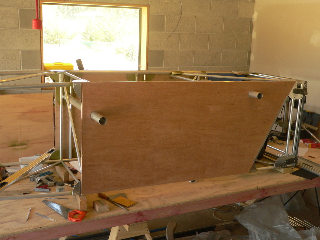
Also today, I started with the the cabane struts.
In wire-braced monoplanes, e.g. the Blériot XI, the cabane struts (generally referred to as the cabane) form the structure above the wings to which the wing's bracing wires are attached.
After I told Jack I bought the 5 cylinder Velie radial, a 85 year old engine from the US:
Good for you buddy!
I was thinking about the engine last night, for the price, you can't beat it. The Big Twin, through Valley Engineering is already 6 grand. Most engines are nearing $10,000. I think the only other thing you need to buy is the silk scarf. I'm real happy for you - Good for you!
Congratulations
Jack
Just bought the Velie engine that I was talking about, just above. It is an 85 year old engine from 1928. A 5 cylinder radial, that is going to look beautiful in front of my Bleriot !!!!!!
It's my best "Bleriot friend" Jack Vanderwerf in the US I have to thank, because he told me about that engine that was for sale in the US, after I showed him the picture above !!!!! So thank you again Jack !!!!
Still hard to believe that I have got it 🙂
Posts under this tag are about the restoration of my 5 cylinder radial Velie engine. Bought it in January 2013, from Jack, in the US, a retired aviator who was cleaning up his shed.
Glenn Peck:
While I was looking to buy this engine, I found this gentleman, Glenn Peck who is currently restoring some Velie engines.
Just want to say that he was a great help while making up my mind about buying the engine. And I am glad I found him, because now while I am building up the machine again (27 Feb 2014, a year later) he has valuable info for me as I found out yesterday. So yes good old internet, and phone !! 🙂
Chad Wille:
I would like to thank Chad as well for all the valuable information regarding the engine he has given me. Chad has made my propeller, but also has a Velie engine like mine. He is not using it anymore but has in the past. Always good to talk with him, and you know he has valuable information that I trust.
Darnelle, my step daughter and her husband Cam came to pick up one of our cars. They are here in New Zealand for a week.
Had to explain every detail of my Bleriot. They thought it was great.
Gary, my wife's ex, popped in to get something from his bus that's parked here at the back, was seriously impressed. We couldn't get rid of him 🙂
Started with the frame for the seat.
Its going to look like this one on below but with a square sitting bit.
Back on the job!!!
Had a little holiday between Christmas and new year. Yesterday and today worked on fitting the fuel tank.
Used EVA foam, so the tank snugly fits "inside" the fuselage. Also made some brackets that need some welding done. These brackets are going to "carry" the fuel tank.
Busy live we have, more people around today.
It was the son of my parents friends who used to have lunch at my parents place when the two of us used to go to primary school 5 million years ago.
Cor and Ingeborg and 2 of their friends could not believe what they saw.
Frank and Sylvia came to have a look at our straw bale house as they have ideas to build one as well.
Afterwards I had to show my plane, as you do! Very impressed they were 🙂
Today we had our Christmas lunch with the family.
Andy, my brother in-law had been following everything on my website.
Today I had semi assembled all the bits I have made so far. The whole fuselage, the rudder and elevator.
Everyone, including Lesley, my mother in-law was very impressed.
For me is was also the first time to see this whole assembly. Even I was impressed. Looking really good ! 🙂
All the family was here today, so tied the rudder and elevator with some string to the fuselage to show them what I am making 🙂
Added the 1 7/8" tube sitting in the carry through for mounting the wing. And also did the dashboard, or that's what its called in a car 🙂
In the last few days I have finished all the diagonals that I could do, and now before I can continue with the seat I have made the control stick, or at least the start of it. This way I can find out how far it needs to be positioned forward so I can start with the tubes carrying the seat 🙂
Yes summer is really slowing me down. So many other little projects and big gardens to maintain.
Every day when we come home from work, we spend at least half an hour in the garden, looking for weeds, planting plants, mowing lawns etc etc.
And then half an hour or more working on the plane, before we start preparing tea. That way there is more time in the weekend.
But before Xmas I am finishing a path with pavers, so that will take a few days, and then before you know it, its the end of the year.
But really enjoying building the Blériot !
Turned the fuselage around again, the right way up, and started on the diagonals.
Also started thinking how I am going to do the seat, or more precisely what framing to create to mount it on. So in the near future I might be doing some work with ply to create a nice authentic looking seat 🙂
But before that I need to put the fuel tank in, as I can't finish the cross tubes and diagonals because they would be in the way.
In the last few days I have done all the cross tubes except for the last one at the back. Will do that one when I attach the back of the fuselage.
(fuselage is shown upside down here)
And yes in case you picked it up, I haven't done the 4 cross tubes that carry the seat and the foot rests. Have something else for those in mind.
Tomorrow some diagonals at the bottom and the top. Starting to look impressive now, won't be long and I will start on the controls and the seat !!!!!!!!
Yesterday and today, I permanently joined the two halves !!!! 🙂
The plan is to put all the cross tubes in (connecting the left and right side), and then drill the 4 holes through the carry through, and fix the firewall into place.
Have finished drilling holes through the engine mount and into the gusset plates of the fuselage, so almost ready to bolt it all together.
Just the carry through's to cut to size and insert in the "holes" before I do that.
Exciting !!!!
Yes the firewall fits!!
In case you don't know, the fire wall (aluminium sheet) sits in between the engine and the pilot.
I even made a 1/2 inch up-stand on the fire wall, that sticks out just outside the fuselage, "pointing" backwards. You can just see it (if you know what you are looking for) on the right here just to the right of the diagonal tube.
The idea is that the 5mm ply wood sheet, nicely slots into it.
Today I marked the plywood panels and the position of the 2 holes for the carry through. I will cut it later when the two sides of the fuselage are joined together.
Next will be the fire wall.
Sounds a bit boring but today I bent the side panels of the fuselage. I did that about 1' behind the rear carry through. So from that point, the two side panels start moving closer together. Also re-adjusted the engine mount a bit with the neighbour who did the welding, and now it fits perfectly !!!!!
Next few jobs on the list are :
I have drilled the 4 holes in the engine mount base for the bolts that stick out at the front of the fuselage!! I can now start the connections between the left and right side of the front half of the fuselage.
Blimey, looks amazing, good on you!
Yes the engine mount is here. It's the base of the frame. I will do the remainder when I have an engine.
The frame also has 4 brackets welded to it that get bolted to the 4 front gusset plates, and 4 brackets for the bracing wires of the landing gear.
PS note the cat un-aware of my exciting new frame.
Took the blocks of the work bench, making it ready to fit the two sides to the engine mount. So hopefully the neighbour who is welding it, finishes it soon 🙂
Riveted 3 of the 4 diagonals in position. I will do the 4th one after the two carry through for the wing have been put in position as I need some room for drilling holes. You can just see that in the photo here, where the second diagonal is just held in position with sticky tape. I will be drilling from the right side into the carry through.
This is not far away!!
In about a week I will fix the two sides of the fuselage to the base of the engine mount. At the same time I will position the fire wall and the two carry through's for the wing, so all very exciting.
I check your website from time to time. You are making great progress I see. That makes me happy. Looking forward to see your plane fly.
( Pascal was involved in the design of this replica of the Blériot XI )
Today and yesterday, I finished coping 4 of the 5 diagonals for the left side of the fuselage.
I am not doing one of them yet, because the control horn for the aileron will be close to that 5th one. So I will wait til I know exactly where the aileron control horn is going to be.
I also finished making the steel brackets that will be welded onto the engine mount. 4 Brackets will be bolted into the 4 gusset plates at the front of the fuselage.
Also some of the brackets that hold the steel wire for bracing the landing gear.
The base of the engine mount, cut, ready to be welded. But before I have that done, I need to get some brackets ready, for bracing the landing gear, and a couple for the cabine.
The steel tubes look a bit bent but that’s just an illusion, they are straight, really 🙂
Have started making diagonal tubes for the side walls of the fuselage, done 2 so far.
Also bought some 1" square tube steel and started cutting it, to make the base of the engine mount. I will be using this when I start joining the two fuselage halves. I figured that it is a lot easier to do it this way than trying to fit the engine mount later on. Also everything will be nicely "square", if that's the right word to use, but you know what I mean 🙂
And then there were 2 sides !!!!
Here is the foot step. Walked into a local engineering workshop. They had a tube bender so I could bend this bit nicely !! As you can see there is some room between the foot step and the vertical tube for the tube that will go diagonally from there.
Front of the left side is finished now (apart from the diagonals).
Ooops, forgot to update you on my progress. Yes by the way we had a nice weekend last week, away from home.
The left side of the fuselage is almost done now. Well I mean the front side using the the 1" longeron. Currently doing a little half circle tube that is on the left side for stepping into the Blériot. Will show you with a photo in one of the next few days, when that is finished.
Sorry guys, there is no work being done on the Blériot.
I am going to Hokitika on the West Coast with my wife for the weekend 🙂
Yes made some progress, the proof is below. Notice how I am using the timber blocks and the clamps. That works really well.
And the next one.
With my son's birthday this weekend, didn't do a lot. Finished the front station and I am about to rivet the second station with the front carry through in it. But I have all evening tomorrow tonight, so should be able to do quite a bit, hopefully 2 more stations.
Hope that's the right word (station) looks strange to me.
Today I coped the two tubes for the first station of the second half, the left side of the fuselage, ready to drill the holes in the two gusset plates and then rivet them.... Buts that's later :-) Can't wait !
Below the very end of the fuselage, YES I have done it. Looking good!!!
For the back half of the fuselage, the part that has no covering, the compression struts are fixed using gusset plates like this one.
Two sizes of tube are used for the longeron, 1" at the front and 7/8" at the back. Today I finished the front of the fuselage. Showing it of in the garden, with Ben the Labrador. Tomorrow planning to finish the back of the fuselage using my extended workbench, 4.8m + 2.4m = 7.2m.
Last one that's covered by the fabric before I get to the open frame of the fuselage, all GOOD !!
Kate's dad dropped off my daughter, and was very impressed when I showed him what I was doing.
Yes that back carry through gusset plate is in place now. Also the centre to centre dimension for the 2 spars or the carry through's is perfect. Going well so far, no problems !
Yesterday I fixed the front carry through in place. Made this gusset plate myself. Didn't like to have the whole wing just bolted in the double 7/8" tubes, so Basically made a bigger gusset plate that strengthens the whole thing. Also the carry through, fits perfectly so all forces are nicely distributed.
And the third "station", at least I think that's how Robert calls it went in today, see below
And who needs Cleco's. I find with the right drill bit size, putting the rivet in, makes it sit perfectly in place. So after every hole I just put the rivet in and it won't move anymore.
Oh yes, I drill all holes in the gusset plate first, before I position it on the tubing.
Today I finished the back carry through gusset plate. Same story here as the front carry through, didn't like the 5/16" bolt going through the two 7/8" tubes. Will install this plate tomorrow !!! Can't wait :-)
Installed the first 2 Gusset plates for the fuselage. All went really well, and I am really happy how it went. No problems, just a few more and its all done !!!
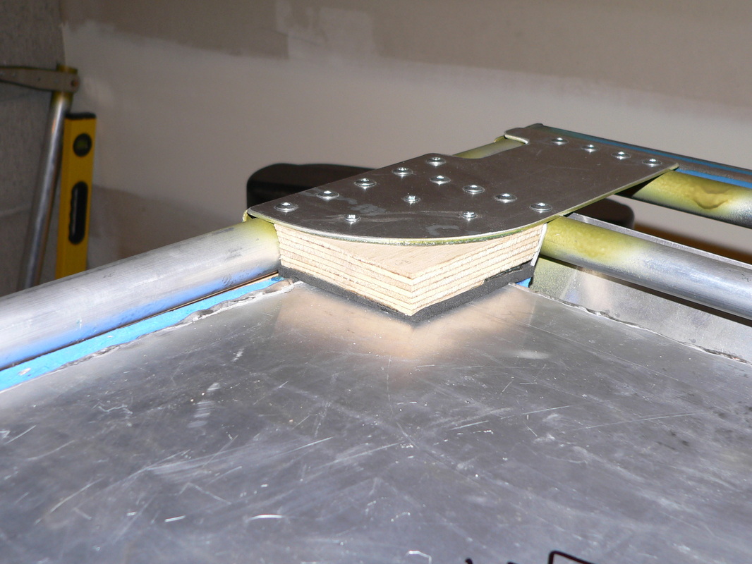
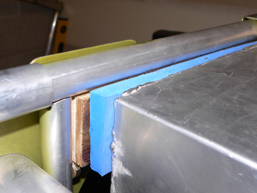
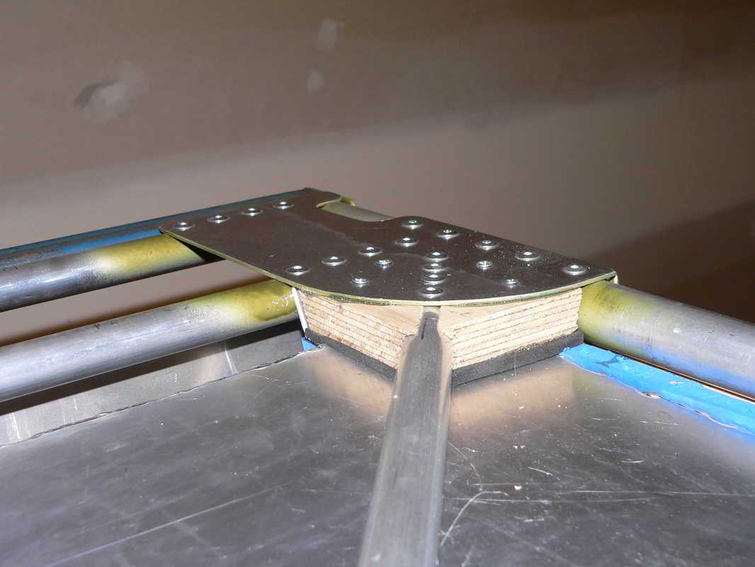
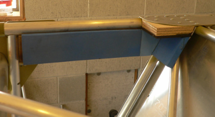
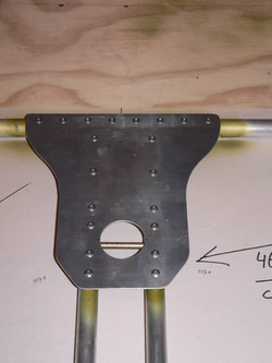
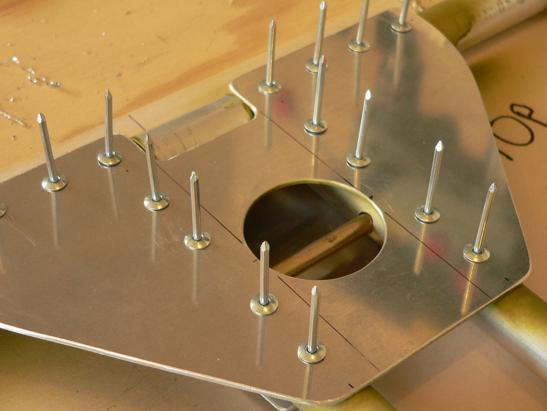
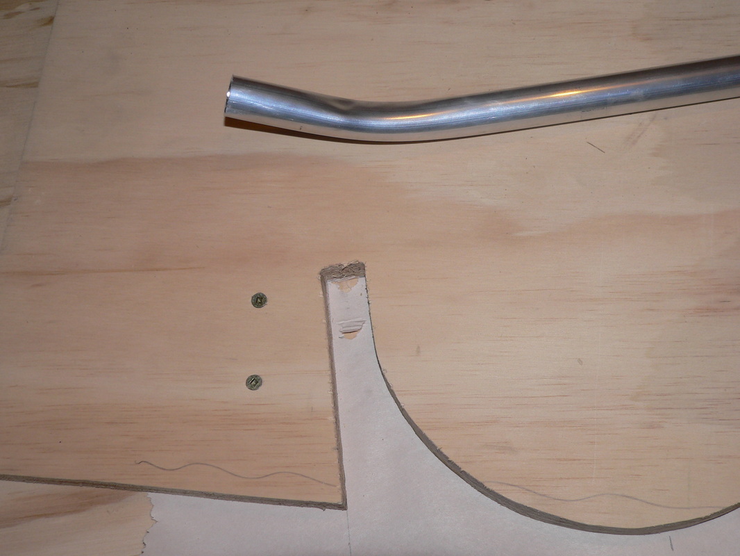
Below is the new gusset plate I made yesterday. So that is at the front of the fuselage at the top. Here you can see how the top horizontal tube of the landing gear goes underneath the longeron, instead of on top.
Tonight I cut two more "vertical" tubes in the drill press with a 1" hole saw. I am getting better at this now. Also drilled the holes for the bottom two gusset plates, so next is the top gusset plate.
Will show you about that one later as that is another special Gert one as well.......
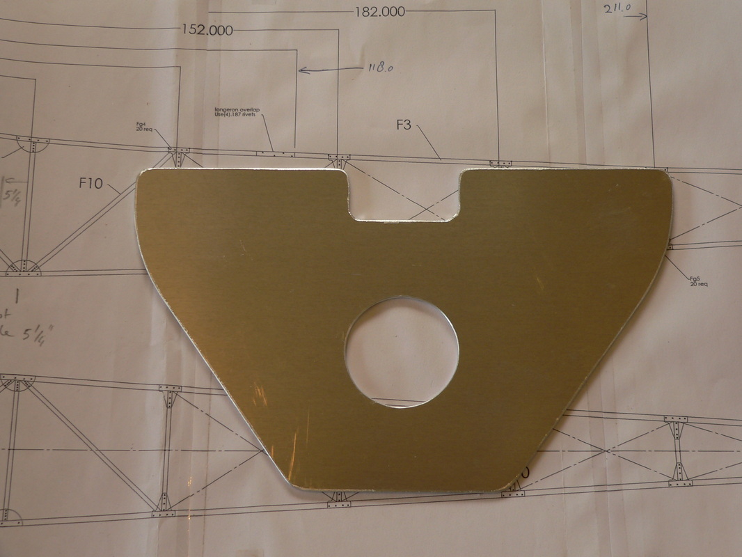
Today I made a new gusset plate to go at the top of the front of the fuselage. Roberts design has the top horizontal tube of the landing gear on top of the two top longerons, but I have decided to put it underneath these longerons. Reason is that this was done in the original Blériot, and it makes more sense to have the weight of the plane push against the bottom of the two top longerons. Also it means that the (don't know what its called) cover that goes over the fuel tank, doesn't have cutouts for this top horizontal tube of the landing gear. Hope it all makes sense, and if not, you will see when its built.
Left gusset is the new one. Right gusset is the original one.
Here is the first vertical tube (the front one) of the side "panel" of the fuselage in place.
You also see the bolt poking out on the far right. It is going to hold the engine mount, a frame of 1" square steel.
At the left you see how I hold the aluminium tube in place while fixing the vertical tubes………
More tomorrow
Screwed most of my timber blocks onto the bench. Looking good !! Using little clamps to keep tube in position where needed, see 2 photos below from here.
My work email system is down at the moment so I was wandering around the web and came across your website. Very nice website!
Not a lot happening this week, lots of Olympics on TV, Great! Watched my step-daughter grooming the horse she owns, for the NZ eventing team - he won the team bronze medal - GREAT!!
But today, I worked on the last preparations before I can start with the fuselage. Made a whole lot of timber blocks, to screw into the bench, to keep the longeron's in place. And because the fuselage of the Blériot is symmetrical, I can take out the first side and put it back upside down using the same blocks, before building the other side on top of the first side. The timber blocks are high enough to hold both sides. Also made ten 2" sleeves that go over the longeron in various places, so all ready for the big job now :-)
Glen, a local contractor popped in to talk about doing some ripping on the land next door.
I had to show him the garage. Immediately he came up with stories of other people in the area flying in their planes. All good !!
Temporarily extended my workbench today, preparing myself for the fuselage. The longeron, see below right is created from 2 tubes, one 1" with the kink in it, and one 7/8".
Without riveting the two together, I am going to build the 2 side panels.
Then I separate the front from the back, and plan to finish the whole front fuselage first. I am doing this because the whole fuselage is something like 7m long, too long to fit in the garage. This way I can stay working in the garage as long as possible. Later on I have to move into our shed, big enough to finish the Blériot XI.
Above you see the beginning of the side frame. The bits of tube there are the vertical tubes to go in between the longeron's. Because the longeron has a kink, I decided to start this way. Once laid out and marked , I determined where the kink was going to be.
Right you see a curved bit of ply (used for elevator) screwed into place to bend the longeron. I did bend all 4 longeron's so next I can start building !!!!! Yeah.
Well here I go.
This is going to be exciting, a big part of the project. I am expecting this to take a good few months. Organized all the tubes now, put a new piece of paper on the workbench, and started making markings on the paper. Almost ready to start !!!!
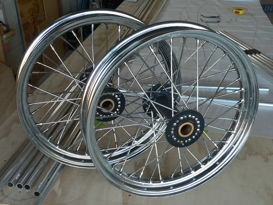
While watching the Olympics tonight, I have put Vaseline on the wheels. A friend said that the metal could easily rust, and Vaseline would prevent it from rusting. So there you go.
That's done now.
Tomorrow back to fuselage !!!
I just saw a pic of a happy pilot! You're starting to realize how truly big this thing is going to be, aren't cha? I've been resisting the urge to ask how things are going, and it's paid off... I’ve got my answer! Good for you!
Today I FINISHED the elevator.
All I had to do was rivet the hinges into the 1" tube
This weekend started working again on the elevator. bending 6 ribs from sheet aluminium. I am not using Robert's supplied aluminium, they are to hard to bend. I am using 6061T6 from a local aviation store. No idea what to do with the original supplied ones, just impossible. My ribs work just fine. The elevator is made from 1" and 1/2" tube.
Almost finished the whole elevator. Need to "connect" the stabilizer and elevator, and then up to the next project, the fuselage !!!!
But first I need to make a few brackets on the wall to start hanging up the bits I have done so far.
Haven't done anything this week as I have been struck with the flu for the last few days. but I am slowly getting on top of it :-)
Didn't finish the whole elevator as I thought I would when I started yesterday, but quite happy how things are going.
Right: my first coped tube, it fits quite well !!
After I did the first gusset plate, I decided to do it differently for all the other ones.
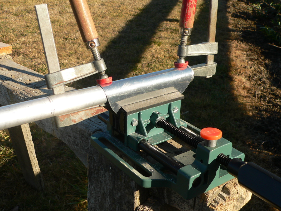
Now I first bend the gusset plate over the right sized tube, with my hands.
Then I put the whole thing in a vice, and leave it there for a minute or so. That vice you see below is so handy, use it for a lot of things !!!!
And this is the first half done. I think that part is called stabilizer. For now, it's without the two middle "spacers". I will put those in just before it gets mounted onto the fuselage.
And then it gets put in place, drilled, de-burred, cleaned and riveted, and bob's your uncle :-)
Started assembling the elevator today.Below: the first joint of the bigger 1" tube and the curved 3/4" tube.Right: the stabilizer, the fixed part of the elevator.
Below: in the center of the stabilizer two 7/8" sleeves. One inside the 1" tube, and one over the two halves made of curved 3/4". This reinforcing is there so bolting onto the fuselage is more rigid.
And started coping the tubes that go in the elevator. I am using a drill press with a vice bolted onto it. Seems to go OK !!
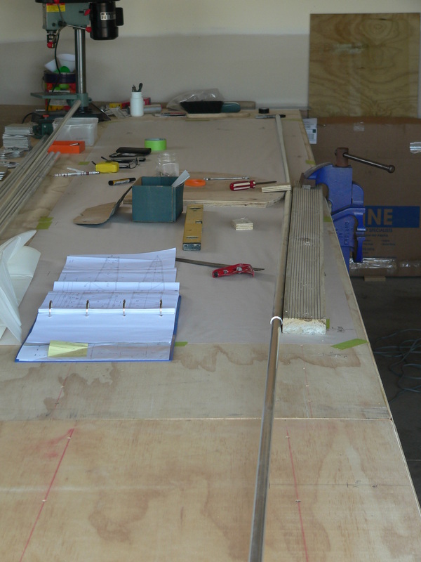
Put paper on the bench to draw the shape of the elevator. Bought the roll of paper about 40 meters for $5, a good investment, because now I can draw all the details on the bench. Plenty of room for calculations, etc etc.What you see here is the front of the elevator, 3/4' tube, and my bending jig. I really like bending this way , with the shot peen in the tube!!!
Wow look at this, all the bits for my next part of the big project, the elevator. Looks like I am going to get most of it done this coming weekend. At this rate I will be finished next month :-) !!!!!
My interest in the Blériot started a couple of years ago when I was afforded the opportunity to sit in Eric's Blériot at Oshkosh.
Have thought often of doing one in wood but not comfortable with the plans that I have come across so far.
Wow I have done it, My first bit of the Blériot is finished !!!!
Around the rudder control horn, I have put an extra gusset plate, so the material for covering the rudder can be fixed nicely.
Gert, for bending the tubes we always use fine sand. The results are the same as when you use "shot peen".
Greetings from Sluis, and we follow your progress.
Hi your website looks awesome, are you having fun yet?? Did you start working on it?? Remember to read and follow the directions.
Haha
Tonight I spent some time in the living room, bending the last two ribs for the rudder. I knew it was going to take a bit more time because my "bender", shown above is just a little bit to short for these two ribs, but they are the only two long ones.
All other ribs are short enough to fit.
Hey, Gert… that’s awesome. I didn’t realize you were building old school! Very unique. I like it.
Today my first job was to make a little "bender". I made it from 2 bits of 4 x 2, 5 hinges and a steel trip. Works great !!! Really happy. The steel strip has a bit of a radius on the end, so when I bend the rib in this case for the rudder, it had a nice radius and no problem with cracking or braking, so that's all good :-)
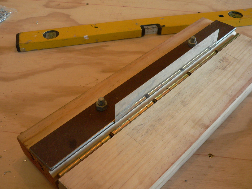
The rudder is almost done now, just two more ribs to do and a few gusset plates.
I now realize why I had the problems bending the outside tube. Robert gave 7/8 inch tube but all photo's I have seen so far and even my drawings suggest that the tube should be 1/2 inch. Spoke with Robert and yes he had made a mistake on his bill of materials.
Nice website, Gert – probably as time consuming as making the plane! keep up the good work!
Good for you!!!
I saw that rudder and I let out a cheer! You did a damn good job. Prior to your email, all I had seen was you beside a lonely work table… Photo document the daylights out of everything you do………. You’ll appreciate it, and so will everyone else.
Luther came with his parents and some friends. Lots of little bits of advice, so that's great !!
Luther Keats, Gavin Keats, Daphne Robson, Joe Dobinson, Marilyn Knowles
My first real day working on the Blériot. The shoot peen did make a big difference. After filling and compacting and more filling up, it just bends without any kinks. Really happy about the result!
Then the first rivet. Wow that riveter goes really well.
It's starting to look like a rudder. Next are four ribs made from sheet material. First I will make a "bender" to bend them.
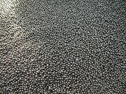
I have my "Shot peen" 1mm little steel balls!! I am going to use them to fill up the aluminium tubes, so when I bend them they shouldn't kink or deform any more.
But wait: I saw the delivery van from Bullet Freight coming into work yesterday, just as I was leaving for home, and I thought oooh that might be for me, because I knew they were used by the supplier. Today I asked the lady at reception, and she said; "yes they were delivering the metal balls, but the bag had split and they were going to reorder it".
Oh no I thought, I won't have it in time for the weekend. So I rang them and they said I could have what was left over from the bag. They are just around the corner from work so just went there and picked it up. It's a paper bag with a little hole in it, so I have almost the whole bag plus what they swept from the floor of the van !!!
Yes, so now I can start bending !!
I started with the rudder today. Made a fixture from ply wood to make the first bend in a 7/8" tube. There are 4 bends with a radius of 6 inch. But when I started I saw the inside wall of the tube started to collapse, so I stopped for now. Not happy with that but surely I will find a solution or this. Maybe it is OK as you can't see this once it is covered, so maybe I just need to continue, and if what you see here is all than it's probably OK.
Posted a question on the Yahoo Airdrome Builders website, see what advice the guy's have for me.
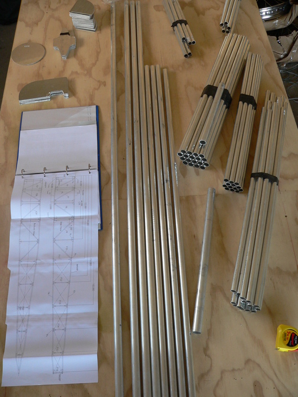
Just unloaded the box. Lots of tubes, fuel tank, 2 wheels, bags with gusset plates rivets and lots of other goodies. Looks great !!!!
If I get the time tomorrow I might start with the Rudder, that will be interesting.
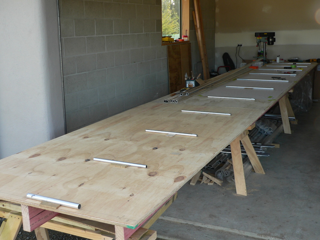
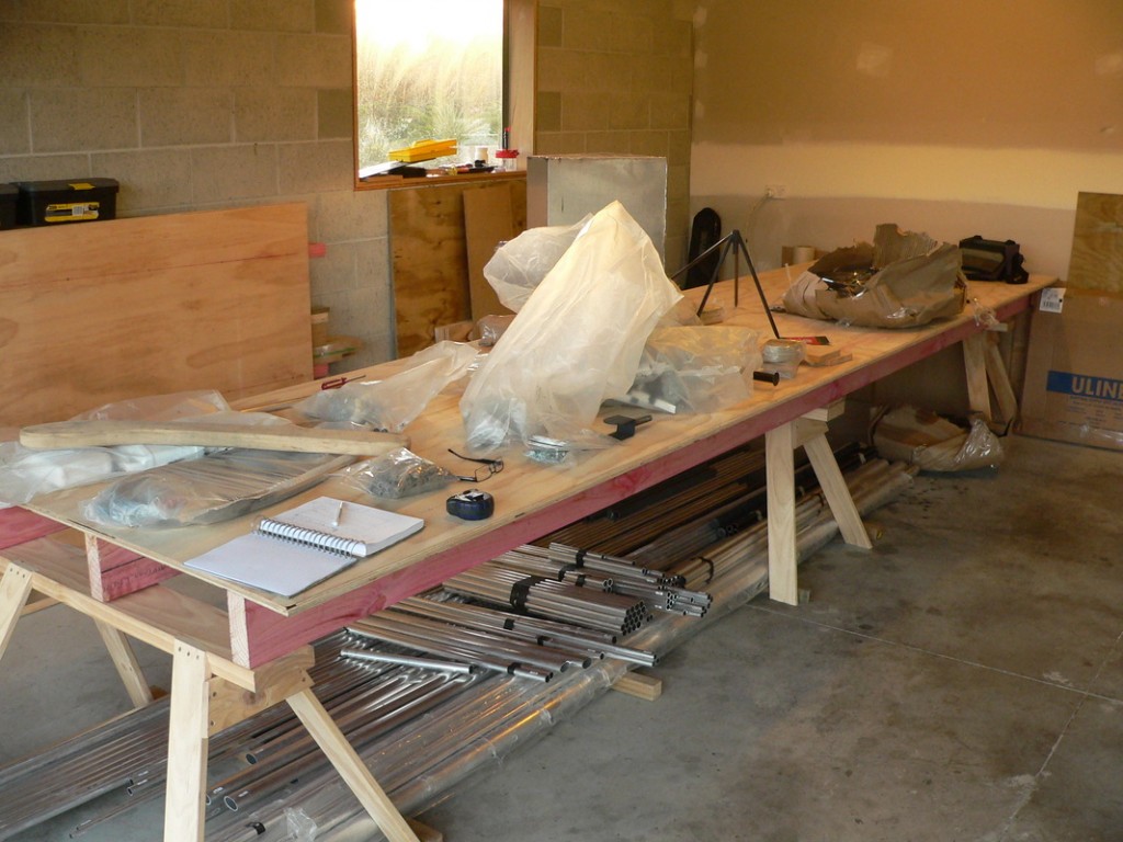
You can see my work bench here. 3 Saw horses, 3 bits of 2 x 6 to support 2 sheets of ply 1.2m x 2.4m. Against the wall on the left you see one more piece of ply with bits of 2 x 6 screwed onto. When I am working on the fuselage, I can then extend the workbench to 7.2m!
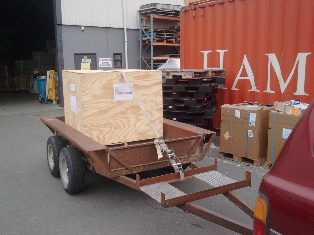
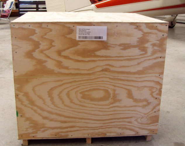
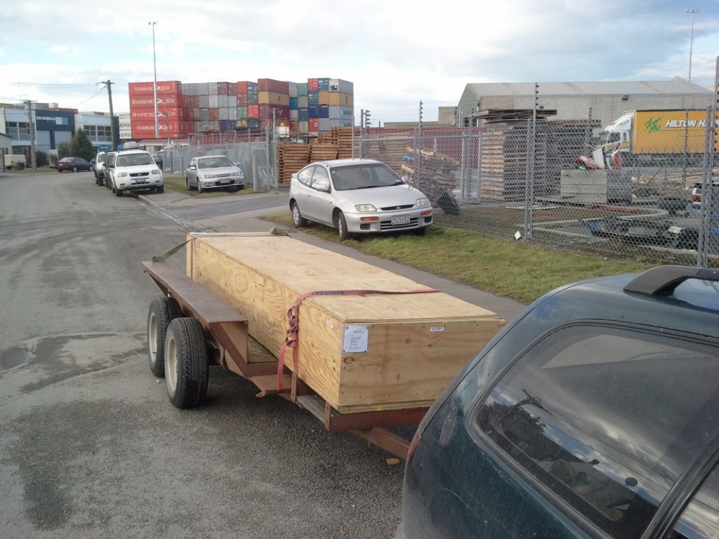
Today I am taking the trailer into work. Picking up the kit set from Hilton Transport Ltd in Heathcote in Christchurch. This was very exciting to finally have that 4m long box on the trailer. At home I quickly took the lid off, that was secured with 100 or more screws.
This is so unreal to finally see all the bits and have them in my hands.
In the last few months I have been studying 1400 photos of Pascal Kremer's Blériot when he was building Roberts first Blériot kit set with Robert. This is going to be GREAT. I quickly emailed all my "plane friends" the good news !
FINALLY, the box for the kit set arrived in Christchurch today.
Just yesterday I said to Nicki, that there could be a letter in the mail that the kit set had arrived, and would you believe it, I got a call on our answering machine from a shipping company that the box had arrived in Auckland !!!!!
Today I got an email from Robert on my Phone when I woke up. YES he has finished packing the kit set, and send it by truck, train and ship to Christchurch New Zealand. More waiting now, but ah well its going to take me 1 or 2 years to build the plane so that doesn't matter.
Finally after a few problems, I managed to transfer the money for the kit set into Robert's bank account in Holden Missouri. I have been talking with him in the weeks before this, so he started the preparations for the kit set early.
Today we are camping at Okains bay near Akaroa as my 50 year birthday present. I started talking about the Blériot and Nicki and I decided that I should build and fly Robert's full scale Blériot. Wow I can't believe that it might be happening, this is just unreal !!! :-).